Ba-2029, Fb-2028 – Daktronics Outdoor LED Scoreboards Installation User Manual
Page 28
22
Electrical Installation
BA-2029
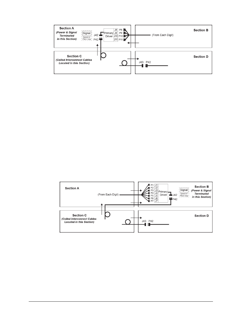
Open the appropriate access panel on the bottom-left cabinet (Section C) to locate the coiled
bundles of interconnect cable coming from the driver, then route and connect the cables as
described below and shown in Figure 25. Additional panels may be opened for easier access.
1. There are seven 9-pin digit harnesses (P1–P7) in the upper-left cabinet (Section A)
that must be routed into the upper-right cabinet (Section B) and connected to the
mating J1–J7 jacks on the Primary Driver.
Note: For models with white digits, the four TIME digits (P1–P4) will connect to the
Secondary Driver (A7) and the rest will connect to the Primary Driver.
2. There are two separate interconnect cables in Section C:
a. Route the 5-pin interconnect cable with the P42 plug up into Section A first then
over into Section B, and connect it to the J42 jack on the Primary Driver.
For models with white digits, this will connect to the Secondary Driver (A7).
b. Route the 5-pin interconnect cable with the J43 jack over into the bottom-right
cabinet (Section D), and connect it to another interconnect cable with the P42 plug.
Note: A separate wired signal (copper or fiber optic) must be terminated to a small
enclosure in Section B to control the speed of pitch digits.
FB-2028
Open the appropriate access panels on the upper-left (Section A) and bottom-left cabinet
(Section C) to locate the coiled bundles of interconnect cable coming from the drivers.
Refer to Figure 26. Additional panels may be opened for easier access.
1. Route the 5-pin interconnect cable with the J43 jack from Section C over into the
bottom-right cabinet (Section D) and connect it to the P42 plug on another
interconnect cable coming from the Secondary Driver.
Figure 24: Power/Signal Connection
– Four Sections, BA-2026 & BA-2028 (Front View)
Figure 25: Power/Signal Connection
– Four Sections, BA-2029 (Front View)