Modular football scoreboards – Daktronics Outdoor LED Scoreboards Installation User Manual
Page 29
Electrical Installation
23
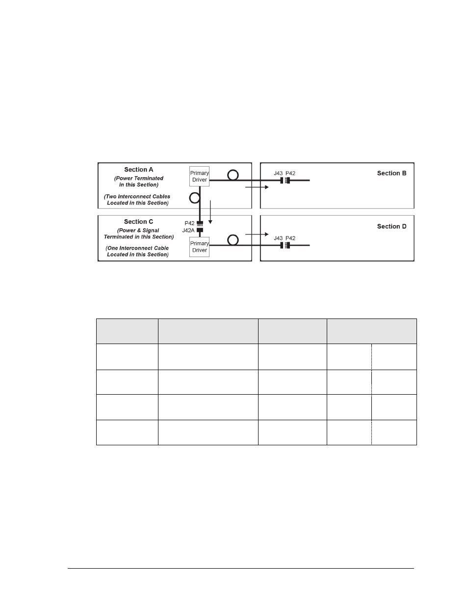
2. There will also be two separate interconnect cables in Section A:
a. Route the 5-pin interconnect cable with the J43 jack over into the upper-right
cabinet (Section B) and connect it to the P42 plug on another interconnect cable
coming from the Secondary Driver.
b. Route the 5-pin (two wire, signal only) cable with the P42 plug down into Section C,
and connect it to the J42A jack on a Y-cable coming from the Primary Driver.
Note: The FB-2028 can be thought of as two scoreboards stacked on top of each other.
Both Primary Drivers require power termination, but only the driver in Section C
requires signal termination from the control location. Refer to Section 3.2 and Section 3.4.
Modular Football Scoreboards
The table below lists the scoreboard sections that do not receive main power or signal:
Information
Shown
Model #
Driver/Power
Supply Location
Power/Signal
Connections
T.O.L. (HOME)
FB-2531, FB-2533, FB-2536,
FB-2538, FB-2540, FB-2545
HOME Score
A1 J1
A1 J50
PS1 J1
T.O.L. (GUEST)
FB-2571, FB-2573, FB-2575,
FB-2577, FB-2579, FB-2583
GUEST Score
A1 J10
A1 J50
PS1 J10
DOWN
FB-2618, FB-2628, FB-2658
TO GO
A1 J3
A1 J42B
Mod 1 J1
PS1 J3
QTR (quarter)
FB-2621, FB-2631, FB-2661
BALL ON
A1 J8
A1 J42B
Mod 4 J2
PS1 J8
The T.O.L., DOWN, and QTR sections may have up to four connections:
Route the 9-pin plug into the adjacent section and connect to the appropriate jack on
the Primary Driver (A1).
Route the 2-pin plug into the adjacent section and connect to the appropriate jack on
the Power Supply (36" and 48” LED digits only).
If the section includes a backlit or electronic caption, a 5-pin plug must be connected
to the power/signal interconnect cable coming from the Primary Driver (A1).
A ribbon cable must be connected between the last module of the DOWN and BALL
ON electronic captions to the first module of the TO GO and QTR electronic captions.
Figure 26: Power/Signal Connection
– FB-2028 (Front View)