Four-section tennis models, Pari-mutuel displays – Daktronics Outdoor LED Scoreboards Installation User Manual
Page 32
26
Electrical Installation
Four-Section Tennis Models
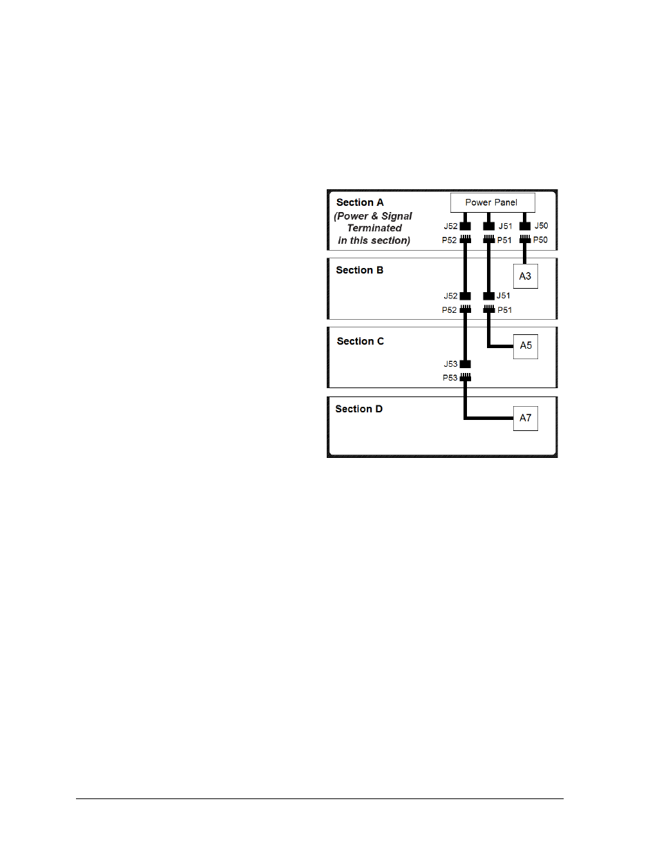
The primary driver and power panel will be located in the top section (Section A). Refer to
the component location drawings attached to the product specification sheets listed in
Appendix A for exact driver locations.
Open access panels as needed to locate the coiled bundles of interconnect cable, then route
and connect the cables as described below and shown in Figure 31.
1. Route the interconnect cable
labeled P50 coming from the A3
driver in Section B up into
Section A and connect it to the
J50 jack coming from the power
panel.
2. Route one end of the interconnect
cable labeled P51 from Section B
up into Section A and connect it
to the J51 jack coming from the
power panel.
3. Route one end of the interconnect
cable labeled P52 from Section B
up into Section A and connect it
to the J52 jack coming from the
power panel.
4. Route the interconnect cable
labeled P51 coming from the A5
driver in Section C up into
Section B and connect it to the
interconnect cable labeled J51.
5. Route the interconnect cable
labeled P52 in Section C up into
Section B and connect it to the interconnect cable labeled J52.
6. Route the interconnect cable labeled P53 coming from the A7 driver in Section D up
into Section C and connect it to the interconnect cable labeled J53.
Pari-mutuel Displays
Each pari-mutuel display model requires power, while one display may receive signal and re-
drive it to other displays (refer to Figure 29 for an example of re-driving signal).
All pari-mutuel displays are composed of two sections. In order for power and signal to reach
both sections, an interconnect cable from the primary driver in one section must be connected
to the driver in the other section. The location of these drivers varies, but the connectors
always include a 5-pin plug labeled P50 and a mating jack labeled J50. Refer to the schematic
drawings in the service manual for detailed driver interconnect diagrams.
Note: Since the PM-2101 has two sections but only one driver, it requires individual digit
harnesses to be routed from the top section down into the bottom and connected to the
appropriate jacks in the driver. Refer to the component location drawing (attached to
product spec sheet) for the proper digit output numbers of the top digits.
Figure 31: Power/Signal
– TN-2652 & TN-2653