Connecting the horn start, Figure 11 – Daktronics HS-200 Horn Start User Manual
Page 14
System Setup & Operations
8
Note: Always install the speakers
tilting down to easily drain and
prevent water from collecting inside.
Note: Always place cables and equipment in areas of minimal
traffic. Cover wires and cables with a mat to prevent accidents.
When plugging in dual banana connectors (Figure 12), the GND
(ground) tab on the plug must line up with the black female jack
for the timing system to work. Remember this when connecting
all dual banana plugs.
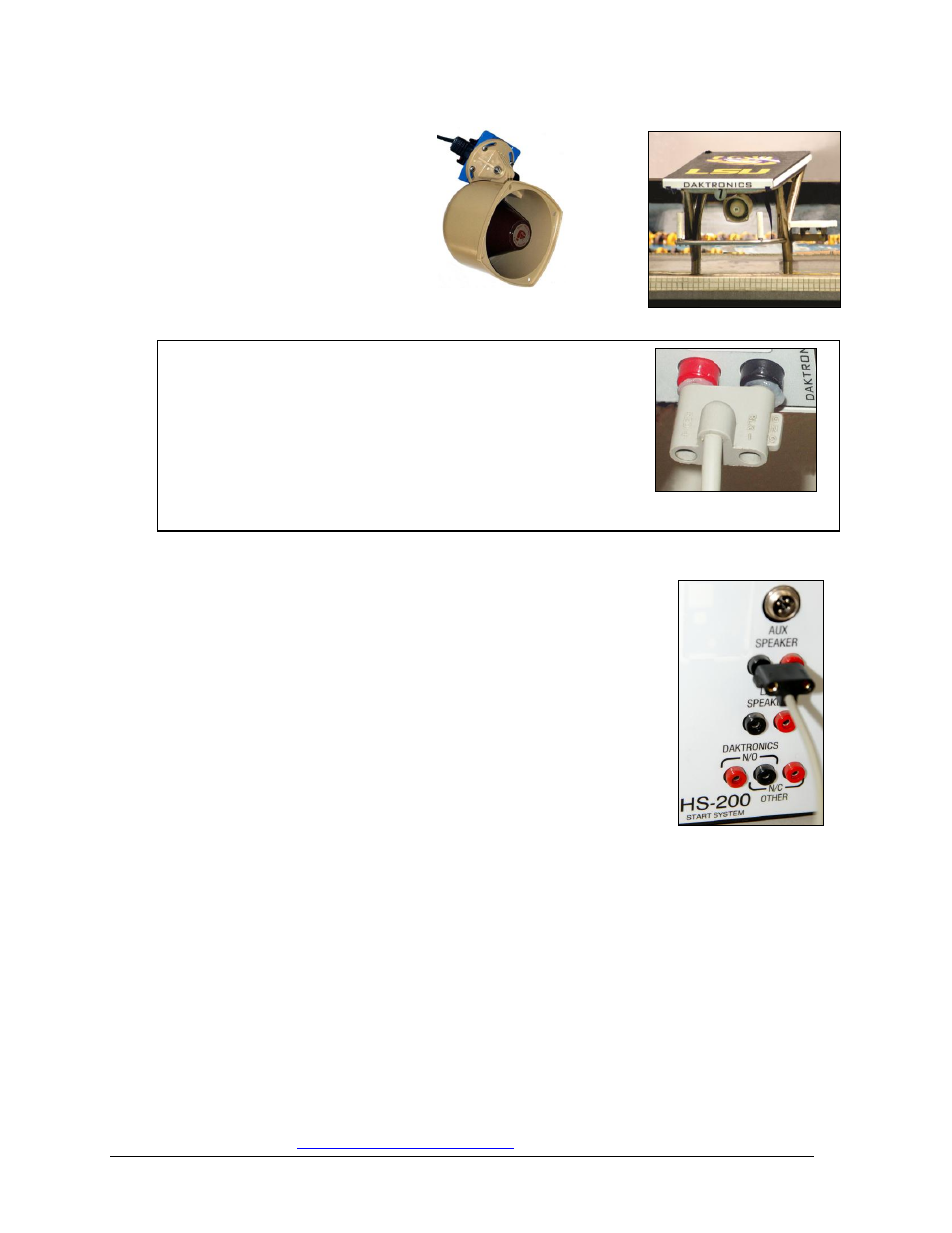
Connecting the Horn Start
Connect the cable from the lane speakers into the jacks labeled
LANE SPEAKERS on the HS-200 connection panels.
Connect the cable from the Auxiliary speaker (Backstroke
speaker) into the jacks labeled AUX SPEAKER on the
HS-200 connection panel as shown in Figure 13.
Connect the cable from the OmniSport 2000 start input J12 into
the jacks labeled DAKTRONICS N/O on the HS-2000
connection panel.
Note: Correct connections are crucial for the horn start
to properly function. Improper plugging may cause
damage to the equipment.
If using the HS-200 horn start with an Omega
®
timing console, connect the start cable
from the Omega console to the N/C OTHER connectors on the HS-200.
If using the HS-200 horn start with a Colorado Timing System console, connect the
start cable from the CTS console to the N/O connectors on the horn start.
Connect the microphone cable into the jack labeled MIC on the HS-200 connection
panel.
Connect a wallpack power supply from the POWER jack to a 120 VAC outlet.
For complete information on Daktronics timing system setup, refer to Section 2 of the
OmniSport 2000 Timing Console and Pro Software Operations Manual (ED-13312),
available online a
Figure 10: Backstroke
Flagpole Speaker
Figure 11: Lane Speaker
Figure 12: Insert GND Side
to Black Female Jack
Figure 13: Horn Start
Connections