Daktronics HS-200 Horn Start User Manual
Page 12
System Setup & Operations
6
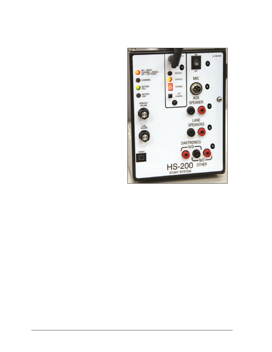
5. ON/OFF switch is the main
power switch. Turn switch to
OFF when the HS-200 horn
start is not being used.
6. The MIC jack is a standard
CB style 4-pin cobra/uniden
microphone connector.
A microphone extension can
be used if it does not exceed
50' (15 m).
7. The AUX SPEAKER jacks
typically connect to the
Auxiliary Speaker cable.
If there are no lane speakers,
plug the Aux Speaker cable
into the LANE SPEAKER
jacks. This will give separate
volume control of the Aux
Speaker and the internal
speaker on the horn start in
addition to each of them
having their own dedicated
amplifier.
8. The LANE SPEAKERS jacks typically connect to the cable from the Lane Speakers.
9. DAKTRONICS N/O and N/C OTHER jacks connect to the timing console start
input. The black jack is the GND tab that the start cable plugs into.
The N/O jack output a Normally Open switch contact—meaning the switch output is
open and closes momentarily to signal the start of the race. The N/C jack output is a
Normally Closed switch contact—meaning the switch output is closed and opens
momentarily to signal the start of the race.
10. These controls and indicators are for the wireless microphone. Refer to Section 3.5
for more information on wireless microphone setup and operation.
Figure 5: HS-200R Connection Panel