Introduction, How to use this manual, Section 1 – Daktronics BA-1518-11 Multi-Section Outdoor LED Scoreboard User Manual
Page 5: Introduction -1, How to use this manual -1, 1 how to use this manual, Disconnect power when the display is not in use, Disconnect power when servicing the display
Section 1: Introduction
1.1 How To Use This Manual
This manual explains the installation of Daktronics Outdoor LED Timing Displays and provides
details for display maintenance. For other questions regarding the safety, installation, operation, or
service of these systems, contact Daktronics. Customer Service Help Desk telephone numbers are
listed on the cover page of this manual. This manual would be referred to as ED12562.
Important Safeguards:
1. Read and understand these instructions before installing the display.
2. Do not drop the control console or allow it to get wet.
3. Properly ground the timer with a grounding electrode at the display location.
4. Disconnect power when the display is not in use.
5. Disconnect power when servicing the display.
6. Do not modify the structure or attach any panels or coverings to the display without the
express written consent of Daktronics, Inc.
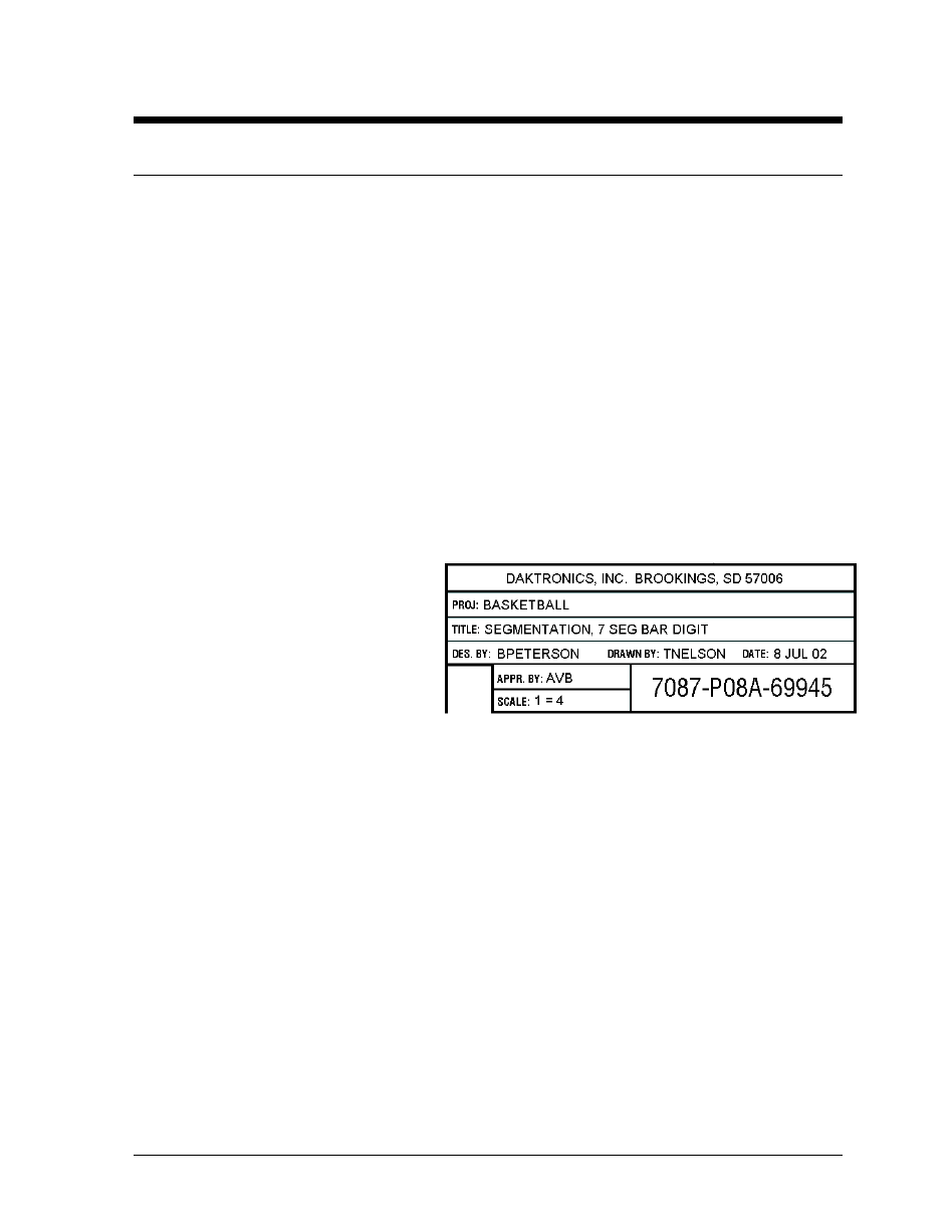
The box at right illustrates the Daktronics drawing numbering system. Daktronics identifies
individual engineering drawings by the
drawing number (7087-P08A-69945 in
the example), which is located in the
lower right corner of the drawing. This
manual refers to drawings by their last set
of digits and the letter preceding them.
The example would be Drawing A-
69945.
Figure 1: Daktronics Drawing Label
Reference drawings are grouped and
inserted in alphanumeric order in the
Appendix.
Listed below are a number of drawing types commonly used by Daktronics, along with the
information that each is likely to provide.
+
System Riser Diagrams: overall system layout from control room to display, power, and phase
requirements.
+
Shop Drawings: fan locations, transformer locations, mounting information, power and signal
entrance points, and access method (front or rear).
+
Schematics: power wiring, signal wiring, panelboard or power termination panel assignments,
signal termination panel assignments, and transformer assignments.
+
Final Assembly: component locations, part numbers, display dimensions, and
assembly/disassembly instructions.
Introduction
1-1
- BA-1524-11 Multi-Section Outdoor LED Scoreboard BA-2007-11 Multi-Section Outdoor LED Scoreboard BA-3718-11 Multi-Section Outdoor LED Scoreboard BA-3724-11 Multi-Section Outdoor LED Scoreboard FB-1424-11 Multi-Section Outdoor LED Scoreboard FB-1624-11 Multi-Section Outdoor LED Scoreboard FB-1830L-11 Multi-Section Outdoor LED Scoreboard FB-1530-11 Multi-Section Outdoor LED Scoreboard MS-2118-11 Multi-Section Outdoor LED Scoreboard SO-1930-11 Multi-Section Outdoor LED Scoreboard FB-1830-11 Multi-Section Outdoor LED Scoreboard MS-2009-11 Multi-Section Outdoor LED Scoreboard SO-1830L-11 Multi-Section Outdoor LED Scoreboard FB-1524-11 Multi-Section Outdoor LED Scoreboard FB-1730-11 Multi-Section Outdoor LED Scoreboard FB-2003-11 Multi-Section Outdoor LED Scoreboard SO-1830-11 Multi-Section Outdoor LED Scoreboard FB-1430-11 Multi-Section Outdoor LED Scoreboard FB-1630L-11 Multi-Section Outdoor LED Scoreboard FB-2002-11 Multi-Section Outdoor LED Scoreboard SO-1624-11 Multi-Section Outdoor LED Scoreboard FB-1630-11 Multi-Section Outdoor LED Scoreboard FB-2001-11 Multi-Section Outdoor LED Scoreboard SO-1424-11 Multi-Section Outdoor LED Scoreboard