Power and signal connection, Connections between sections, Power and signal connection -3 – Daktronics BA-1518-11 Multi-Section Outdoor LED Scoreboard User Manual
Page 37: Connections between sections -3
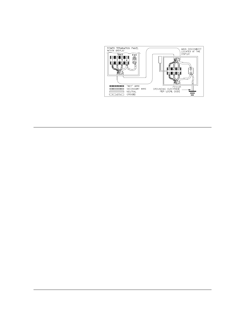
Installation with Only a Neutral Conductor Provided
Installations where no grounding conductor is provided must comply with Article 250-32 of
the National Electrical Code. If the installation in question meets all of the requirements of
Article 250-32, the following guidelines must be observed:
+
Connect the grounding
electrode cable at the local
disconnect, never at the
display entrance
enclosure.
Figure 5: Installation with Only Neutral Provided
+
Use a disconnect that
opens all of the
ungrounded phase
conductors.
+
The neutral and the ground
conductors should be
bonded in the display
power enclosure.
7.2 Power and Signal Connection
Reference Drawings:
Components 8/16 Pos Power and Signal Entrance ............................. Drawing A-109114
Components 2/4 Pos Power and Signal Entrance ............................... Drawing A-125977
Route power and signal cables into the scoreboard from the rear. There are two knockouts for conduit
connection in the back. All wires connect to the entrance plate. Drawings A-109114 and A-125977
illustrate the two types of entrance panels.
To gain access to the entrance panel, open the access door or digit panel and remove the cover from
the entrance enclosure. Refer to Section 4 and Component Locations drawings for the access
location for your scoreboard.
Connect the power and signal cables to the entrance panel as shown in Drawing A-109114 and A-
125977.
t
Connections Be ween Sections
There are several cables in the slave sections of the scoreboard, which must be connected to a
panel in the master section (refer to Section 4). Route these cable through the 2 1/2" holes in
the connecting sides of the various sections when mounting the scoreboard.
To gain access to the entrance panel, open the access door on the front of the scoreboard.
Refer to Section 4 for the location of the access door for the model of your scoreboard.
Pull the cables from the other sections and route them to the bottom of the interconnect panel.
Connect the plugs on the cables to the connecting jacks in the interconnect panel. Match the
numbers on the plugs with the numbers on the jacks and insert.
Electrical Installation
7-3
- BA-1524-11 Multi-Section Outdoor LED Scoreboard BA-2007-11 Multi-Section Outdoor LED Scoreboard BA-3718-11 Multi-Section Outdoor LED Scoreboard BA-3724-11 Multi-Section Outdoor LED Scoreboard FB-1424-11 Multi-Section Outdoor LED Scoreboard FB-1624-11 Multi-Section Outdoor LED Scoreboard FB-1830L-11 Multi-Section Outdoor LED Scoreboard FB-1530-11 Multi-Section Outdoor LED Scoreboard MS-2118-11 Multi-Section Outdoor LED Scoreboard SO-1930-11 Multi-Section Outdoor LED Scoreboard FB-1830-11 Multi-Section Outdoor LED Scoreboard MS-2009-11 Multi-Section Outdoor LED Scoreboard SO-1830L-11 Multi-Section Outdoor LED Scoreboard FB-1524-11 Multi-Section Outdoor LED Scoreboard FB-1730-11 Multi-Section Outdoor LED Scoreboard FB-2003-11 Multi-Section Outdoor LED Scoreboard SO-1830-11 Multi-Section Outdoor LED Scoreboard FB-1430-11 Multi-Section Outdoor LED Scoreboard FB-1630L-11 Multi-Section Outdoor LED Scoreboard FB-2002-11 Multi-Section Outdoor LED Scoreboard SO-1624-11 Multi-Section Outdoor LED Scoreboard FB-1630-11 Multi-Section Outdoor LED Scoreboard FB-2001-11 Multi-Section Outdoor LED Scoreboard SO-1424-11 Multi-Section Outdoor LED Scoreboard