Schematic, Led drivers, Segmentation and digit designation – Daktronics BA-1518-11 Multi-Section Outdoor LED Scoreboard User Manual
Page 42: Schematic -4, Led drivers -4, Segmentation and digit designation -4
8.3 Schematic
Refer to Section 5 for a complete listing of the schematics for the Daktronics multi-section outdoor
LED scoreboards. The drawings diagram the power and signal inputs and all wiring for each
scoreboard model.
8.4 LED
Drivers
Reference Drawings:
16 Column LED Driver II Specifications............................................... Drawing A-134371
In the scoreboard, the LED drivers perform the task of switching digits on and off. Refer to
Drawing A-134371.
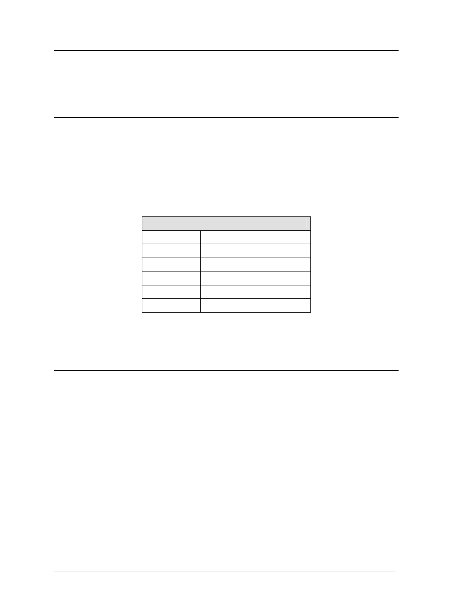
Each driver has up to19 connectors providing power and signal inputs to the circuit and outputs to
the digits and indicators. The connectors function as follows:
16-Column LED Driver
Connector No.
Function
1 – 16
Output to digits and indicators
17 Controls
power/signal
18
Power input for outputs 1-8
19
Power input (120V) for driver
20
Power input for outputs 9-16
Output connectors 1 through 16 each have nine pins. Pin 7 provides power (hot) to the digit or
indicators wired to that connector. The other eight pins provide switching connections.
8.5 Segmentation
and Digit Designation
Reference Drawing:
Segmentation, 7 Segment Bar Digit ...................................................... Drawing A-38532
In each digit, certain LEDs always go on and off together. These groupings of LEDs are referred to
as segments. Drawing A-38532 illustrates digit segmentation. It also details which connector pin is
wired to each digit segment and the wiring color code used throughout the display.
The component locations drawings listed in Section 4 specify the driver connectors controlling the
digits. Numbers shown in hexagons in the upper half of each digit indicate which connector is wired
to that digit.
Maintenance and Troubleshooting
8-4
- BA-1524-11 Multi-Section Outdoor LED Scoreboard BA-2007-11 Multi-Section Outdoor LED Scoreboard BA-3718-11 Multi-Section Outdoor LED Scoreboard BA-3724-11 Multi-Section Outdoor LED Scoreboard FB-1424-11 Multi-Section Outdoor LED Scoreboard FB-1624-11 Multi-Section Outdoor LED Scoreboard FB-1830L-11 Multi-Section Outdoor LED Scoreboard FB-1530-11 Multi-Section Outdoor LED Scoreboard MS-2118-11 Multi-Section Outdoor LED Scoreboard SO-1930-11 Multi-Section Outdoor LED Scoreboard FB-1830-11 Multi-Section Outdoor LED Scoreboard MS-2009-11 Multi-Section Outdoor LED Scoreboard SO-1830L-11 Multi-Section Outdoor LED Scoreboard FB-1524-11 Multi-Section Outdoor LED Scoreboard FB-1730-11 Multi-Section Outdoor LED Scoreboard FB-2003-11 Multi-Section Outdoor LED Scoreboard SO-1830-11 Multi-Section Outdoor LED Scoreboard FB-1430-11 Multi-Section Outdoor LED Scoreboard FB-1630L-11 Multi-Section Outdoor LED Scoreboard FB-2002-11 Multi-Section Outdoor LED Scoreboard SO-1624-11 Multi-Section Outdoor LED Scoreboard FB-1630-11 Multi-Section Outdoor LED Scoreboard FB-2001-11 Multi-Section Outdoor LED Scoreboard SO-1424-11 Multi-Section Outdoor LED Scoreboard