Diagnostic leds, Replacing a driver, 7 modules – Daktronics CR-2004 Multi-Section Cricket Scoreboard User Manual
Page 45: Modules, N 6.7
TNMC Troubleshooting & Maintenance
39
Connectors J25 and J26 control Home and Guest displays. When the ribbon cable is plugged
into J25, the TNMC displays home team information. In the opposite message center, the
signal cable should be plugged into the J26 connector to display guest information.
J19 is the connector for the address plug. To display BATSMAN names, the display address
must be set to “221”. Team names must be set to address “222”, and the HOW OUT display
must be set to address “223” and plugged into J25. Refer to Drawing A-115079 in Appendix
A for more information on setting the driver address.
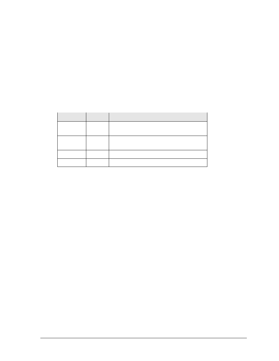
Diagnostic LEDs
The following table explains the functions of the primary diagnostic LEDs on the 4 Column
MASC/MCAST drivers:
LED Name
Color
Illumination Summary
(CL) RX
Red
Steady on or blinking when the driver is receiving
signal and off when there is no signal
(CL) TX
Green
Steady on or blinking when the driver is
transmitting and off when there is no signal
Power
Green
Steady on to indicate the driver has power
Status
Amber
Blinking to indicate driver is running
Replacing a Driver
1. Access the internal components using the appropriate Front/Rear Access method
described in Section 6.5.
2. Disconnect all power and signal connectors from the driver by squeezing together the
locking tabs and pulling the connectors free.
Note: It may be helpful to label the cables to know which cable goes to which
connector when reattaching a driver.
3. Remove the four nuts holding the driver in place.
4. Position a new driver over the screws and tighten the nuts.
5. Reconnect all power/signal connectors.
6. Ensure the driver is set to the correct address.
7. Power up and test the scoreboard/display to see if changing the driver has resolved
the problem.
6.7 Modules
Each module assembly is made up of a module housing (containing LEDs and the driver) and
a louver assembly. Individual components such as louvers can be removed for service, but
Daktronics recommends that the module be kept intact and that the entire assembly be sent in
for repair or replacement.