For displays built before september 2009 – Daktronics CR-2004 Multi-Section Cricket Scoreboard User Manual
Page 44
38
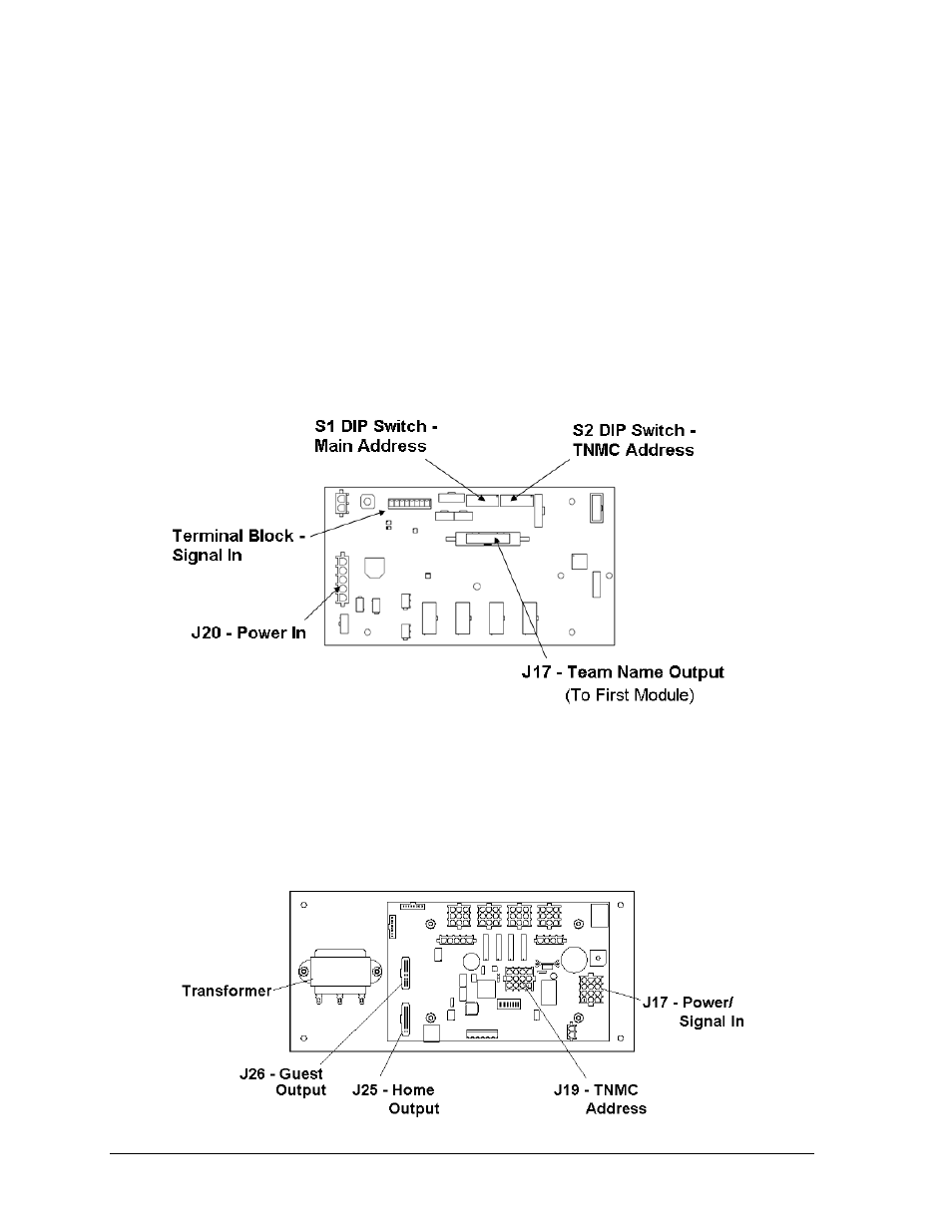
TNMC Troubleshooting & Maintenance
The display driver receives signal from the control console via a signal surge arrestor card
and sends data to the modules. Refer to Section 6.4 for more information on signal routing.
The driver itself is detailed in Drawing A-793970 in Appendix A. Figure 27 illustrates some
of the primary jacks and switches on the 4 Column MCAST display driver.
The S2 DIP switch controls Home and Guest display. When the #5 switch is ON, the driver
sends guest team information to the display. In the opposite message center, the switch
would be set to OFF, and home information would be displayed.
The S2 DIP switch is also used to set the address (switches #1-4). With switches 1-4 off, the
address setting equals “221”. This is the address needed to display BATSMAN names. Team
names must be set to address “222”, and the HOW OUT display must be set to address “223”
with the #5 switch OFF (home). Refer to Drawing A-328274 in Appendix A for more
information on setting the driver address.
For Displays Built Before September 2009
The display driver receives signal from the control console via a signal surge arrestor card
and sends data to the modules. Refer to Section 6.4 for more information on signal routing.
The driver itself is detailed in Drawing A-166216 in Appendix A. Figure 28 illustrates a
display control assembly with a 4-column MASC driver.
Figure 27: 4 Column MCAST Driver
Figure 28: Control Assembly (4 Column MASC Driver)