Radio settings, 4 signal connection, Signal connection – Daktronics CR-2004 Multi-Section Cricket Scoreboard User Manual
Page 24
18
Electrical Installation
Radio Settings
If a radio receiver is installed, the radio Broadcast and Channel settings will be displayed in
on the scoreboard during the POST. These values must match the settings in the control
console (refer to the manual listed in Section 1.4). Refer to Section 5.6 for more information
on radio installations.
4.4 Signal Connection
Signal cabling is routed into the scoreboard
from the rear through plastic plugs for conduit
connection. If no conduit knockouts are
available, installers will have to drill holes into
the back sheet of the scoreboard to allow
entrance of power wires. Note that systems
with radio control do not require external
signal wiring to the display.
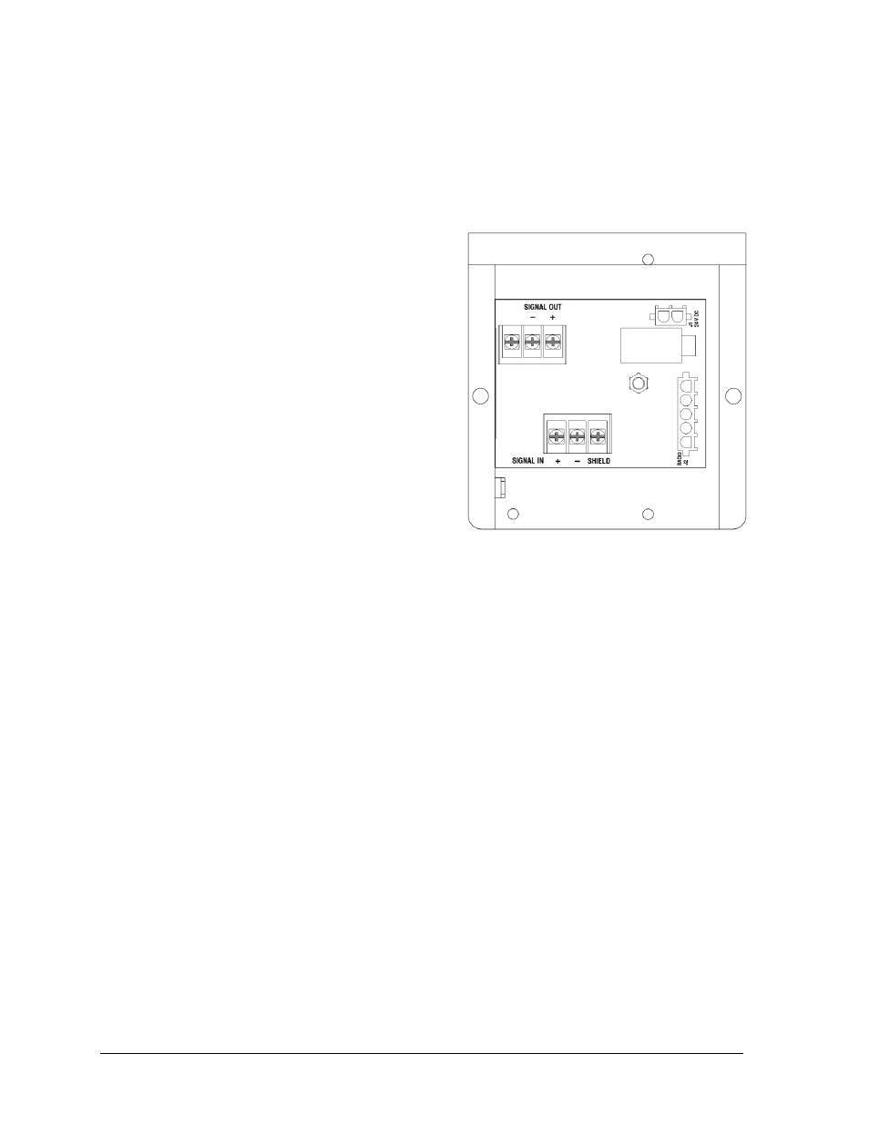
All signal wiring terminates at the enclosure
shown in Figure 14, located in the lower-right
corner of the scoreboard (when viewed from
the front). Refer to Drawing A-327249 in
Appendix A for precise signal termination
location.
1. Route the signal cables via conduit into
rear of scoreboard.
2. Look for a warning label similar to Figure 11 to locate the appropriate access panel
to the signal enclosure.
3. Loosen the screws or latches to open the access panel.
4. Route the signal cables up through the bottom of the signal enclosure.
5. Use a Philips screwdriver to loosen the two screws, and then lift the enclosure cover
up and off the keyholes.
6. At the SIGNAL IN terminal block, connect the signal cables as follows:
Red signal wire to positive (+) terminal
Black signal wire to negative (-) terminal
Silver wire to SHIELD terminal
7. Reattach the metal enclosure cover and secure the access panel.
8. At the control location, connect a 9-pin female to 25-pin male cable (Daktronics part #
W-1249) between the J6 jack on the back of the All Sport 5000 and an available serial
(COM) port on the cricket scoring computer.
Note: Refer to Appendix B for more information on setting up the TCS software.
9. For wired setups, also connect a signal cord from the J-box into jack J1, J2, or J3 on the
back of the All Sport 5000 controller.
For signal cable, Daktronics recommends, as a minimum, single-pair, shielded cable, 22 AWG
(Daktronics part number W-1077). Two-pair shielded cable (part W-1234) is preferred.
Figure 14: Signal Enclosure w/ Cover Removed