Connection – Daktronics CR-2004 Multi-Section Cricket Scoreboard User Manual
Page 22
16
Electrical Installation
Installation with Only a Neutral Conductor Provided
Installations where no grounding conductor is provided must comply with Article 250-32 of
the National Electrical Code. If the installation in question meets all of the requirements of
Article 250-32, the following guidelines must be observed:
Connect the grounding electrode cable at the local disconnect, never at the display
driver/power enclosure.
Use a disconnect that opens all of the ungrounded phase conductors.
Connection
Power cabling is routed into the scoreboard from the rear through plastic plugs for conduit
connection. If no conduit knockouts are available, installers will have to drill holes into the
back sheet of the scoreboard to allow entrance of power wires.
All power wiring terminates at the enclosure shown in Figure 12, located in the lower-right
corner of the scoreboard (when viewed from the front). Refer to Drawing A-327249 in
Appendix A for precise power termination location.
1. Route the power cables via conduit into rear of
scoreboard.
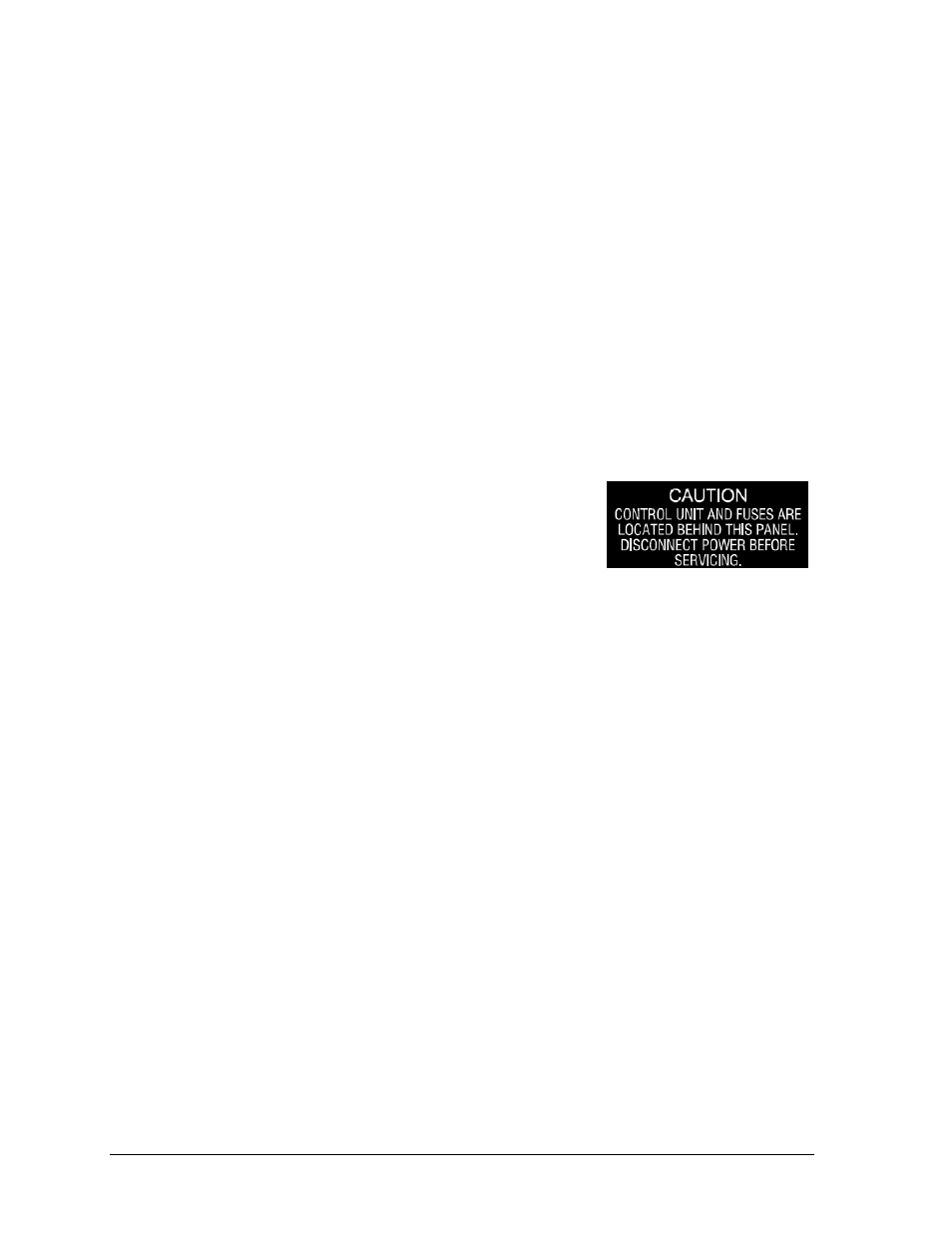
2. Look for a warning label similar to Figure 11 to
locate the appropriate access panel to the power
breaker enclosure.
3. Loosen the screws or latches to open the access panel.
4. Route the power cables up through the bottom of the power enclosure.
5. Use a Philips screwdriver to loosen the two screws, and then lift the enclosure cover
up and off the keyholes.
6. Connect the power cables as follows:
Neutral (white) wire to NEUT.
Live wire to LINE 1 (black)
Live wire to LINE 2 (red) – 120 V installations only
Ground wire (green/yellow) to the grounding buss bar, E41
7. Reattach the metal enclosure cover and secure the access panel.
Note: If a power receptacle is needed to operate the control console at the scoreboard for
troubleshooting, Daktronics recommends that an installation electrician provides a 240 or
120 V outlet close to the disconnect box specifically for this purpose.
Figure 11: Power Warning Label