Section 3: mechanical installation, 1 footings & beams, 2 lifting the scoreboard – Daktronics CR-2004 Multi-Section Cricket Scoreboard User Manual
Page 13: Section 3, Mechanical installation, Footings & beams, Lifting the scoreboard
Mechanical Installation
7
Section 3:
Mechanical Installation
Mechanical installation consists of installing concrete footing and steel beams and mounting the
scoreboard and accompanying ad panels to the beams.
3.1 Footings & Beams
Drawing B-268714 in Appendix A shows the recommended number of beams and spacing
between them.
The column and footing size dimensions are to assist with estimating installation costs.
They are estimates only and are not intended for actual construction purposes. Be sure that
the installation complies with local building codes and is suitable for the particular soil and
wind conditions. The columns, footings, and all connection details must be designed and
certified by a professional engineer licensed to practice in the state of the installation.
Note: Daktronics does not assume any liability for any installation derived from the
information provided in this manual or installations designed and installed by others.
3.2 Lifting the Scoreboard
Larger scoreboard sections and message centers are shipped equipped with eyebolts used to
lift them. The eyebolts are located along the top of the cabinet for each scoreboard section.
Daktronics scoreboards use
1
/
2
" and
5
/
8
" shoulder-type eyebolts mounted to a
1
/
8
" aluminum
plate or steel nut plate.
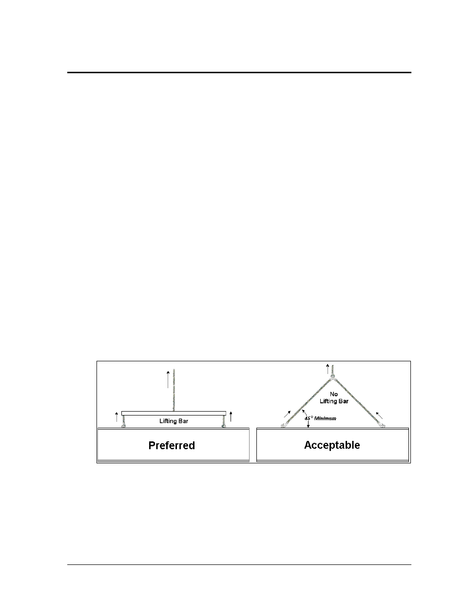
Daktronics strongly recommends using a spreader bar, or lifting bar, to lift the display.
Spreader bars ensure the force on the eyebolts remains straight up, minimizing lifting stress.
Figure 4 illustrates the preferred scoreboard lifting method on the left and an acceptable
alternative lifting method on the right. When lifting the display:
Use a spreader bar if possible.
Use every lifting point provided.
Figure 4: Lifting Methods