3 scoreboard mounting, Scoreboard mounting – Daktronics CR-2004 Multi-Section Cricket Scoreboard User Manual
Page 14
8
Mechanical Installation
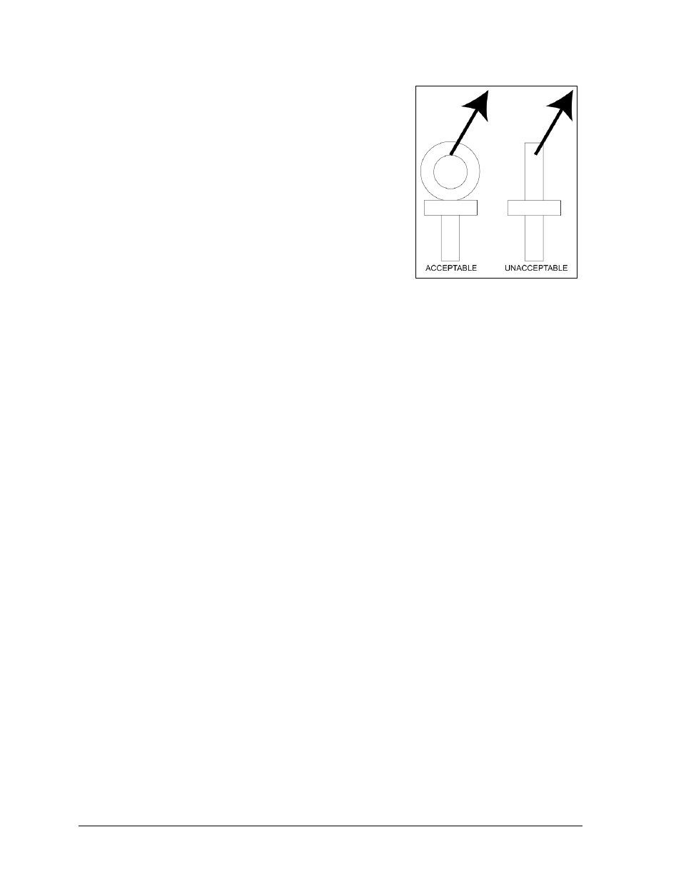
Cables and chains attached to the eyebolts and directly to
a center lifting point, as shown in the right-hand example
in Figure 4, can create a dangerous lateral force on the
eyebolts and may cause the eyebolts to fail. The smaller
the angle between the cable and the top of the display, the
lighter the sign must be to safely lift it. If this method
must be used, ensure a minimum angle between the chain
and scoreboard of at least 45 degrees.
Do NOT attempt to lift the display if the angle is less than
45 degrees. Exceeding load angles or weight limits could
cause the bolts in the scoreboard cabinet to buckle,
resulting in serious damage to the scoreboard or injury to
personnel. Also, loads should be applied directly in the
plane of the eyebolt as shown in Figure 5.
Note: Daktronics assumes no liability for damages resulting from incorrect setup or
lifting methods. Eyebolts are intended for lifting only. Do not attempt to permanently
support the display by the eyebolts.
If installers remove the eyebolts, plug the holes with bolts and the rubber washers that are
used with the eyebolts. Apply silicone or another waterproof sealant to the eyebolt openings.
Also inspect the top and sides of the display for any other holes or openings that may allow
moisture to enter the display and plug and seal those openings.
3.3 Scoreboard Mounting
In typical multi-section installations, the lower scoreboard is installed first and secured to the
support beams. The next section is then placed atop or above the lower section and attached
to the beams. There are cables extending from the top of the lower sections. Guide these
cables into the holes in the bottom of the upper sections for later connection.
Note: Refer to Section 4.5 for more information on the power/signal connections
between sections.
The CR-2004 scoreboard is typically mounted in one of two ways:
1) clamped to vertical beams using mounting angles and long, threaded rods
2) permanently welded to tubular horizontal supports.
Figure 5: Eyebolt Plane Load