Crest Electronics CRE57000 TRAIN ENGINEER REVOLUTION MANUAL User Manual
Page 32
32
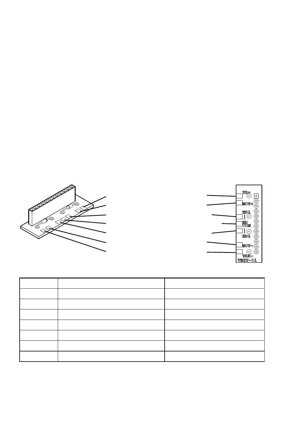
to accept the receiver. To facilitate custom installations, a Adaptor Plug is provided.
The Adaptor Plug has a 12 position socket. Wire the Adaptor Plug to your locomotive
with the connections as shown below.
1) POWERING THE Revolution TE. The Revolution TE is designed to work
from either track power or on board battery power of at least 12 volts DC to a
maximum of 24 volts DC. The receiver is self-protected for polarity and input
current. However, if you use a battery, you should install a 3-amp fuse directly
from the battery before any other wiring is connected. The fuse will protect your
wiring and the battery from damage in case of an accidental short circuit.
2) ISOLATE THE MOTOR(S). The motor(s) MUST be isolated from ALL other
wiring before the Revolution TE can be installed in a locomotive. This is critically
important. Failure to isolate the motors will cause the receiver to malfunction or
possibly fail. After you have located and disconnected the motor wires from the
locomotive, use an ohmmeter to check the resistance between the motor wires and
any other wires that you can find in the locomotive. If any connection is indicated
at all, locate the connection and isolate the motor wires.
3) ADAPTOR PLUG CONNECTIONS. All wiring connections should be soldered
and insulated with heat shrink tubing or electrical tape.
I.D.
USE
TRADITIONAL WIRE COLOR
TR+
RIGHT SIDE TRACK PICK-UP
Black (BLK)
MOT+
MOTOR POSITIVE POWER
Gray (GRY)
HD1
REAR HEADLIGHT NEGATIVE
Yellow (YEL)
HD COM
FRONT HEADLIGHT POSITIVE
Blue (BLU)
HD2
FRONT HEADLIGHT NEGATIVE
White (WHT)
MOT-
MOTOR NEGATIVE POWER
Orange (ORG)
TRK-
LEFT SIDE TRACK PICK-UP
Red (RED)
Connect the motor wires: Solder the motor’s Right Side terminal to the Adaptor
Plug at MOT+. Solder the motor’s Left Side terminal to MOT-.
Connect the power wires: For track power installations, solder the Right Side
power pick-ups to TR+. Solder the Left Side power pick-ups to TRK-. For
Battery Power installations, Battery installations should include a 3-amp fuse in
TR+ RIGHT SIDE TRACK PICK-UP
TRK- LEFT SIDE TRACK PICK-UP
HD1 REAR HEADLIGHT NEGATIVE
HD2 FRONT HEADLIGHT NEGATIVE
HD COM FRONT HEADLIGHT POSITIVE
MOT+ MOTOR POSITIVE POWER
MOT- MOTOR NEGATIVE POWER
TOP
BOTTOM