Crest Electronics CRE57000 TRAIN ENGINEER REVOLUTION MANUAL User Manual
Page 18
18
ADVANCED OPERATIONS, INSTALLATIONS AND PROGRAMMING
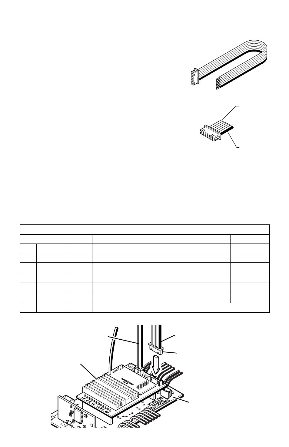
AUXILIARY CONTROL HARNESS
An Auxiliary Control Harness is supplied with the
Revolution TE Receiver. The Auxiliary Control
Harness plugs into a seven pin auxiliary wiring
connector at one end of the receiver circuit board.
The wires, which correspond to keys 1 thru 6 on the
transmitter, are connected to control functions of your
choice.
NOTE: The functions listed in the table below
represent how we envisioned the system to operate.
This does not mean to say that this is the only way that
you can use each of the six functions. More important is
that you assign a purpose to each auxiliary function and
stay consistent from one locomotive to the next so that
you know which key does what on each of your locomotives.
The six switch positions will need to be connected to the accessory you wish to
control with the Transmitter. Please refer to the manufacturer’s instructions for
connecting sound triggers when using third party sound systems.
The six functions of the Auxiliary Control Harness are independently programmable
and intended to operate as follows:
AUXILIARY CONTROL HARNESS
Wire #/Color Tx Key
Typical Use
Setting
1 Blue
1
Horn/Whistle sound
Momentary
2 Green
2
Bell sound
Latching
3 Yellow
3
Brake sound
Momentary
4 Orange
4
Other sound
Momentary
5 Red
5
Running/Cab/Ditch Lights
Latching
6 Brown
6
Smoke
(use with CRE57073 Smoke Control Board)
Latching
7 Black
N/A Common (ground) for all functions
Engine Main
Circuit Board
Receiver
Auxiliary Control
Harness
Remote Link
Switch Harness
Black Wire
1 - Blue
2 - Green
3 - Yellow
4 - Orange
5 - Red
6 - Brown
7 - Black
Wire Color I.D.