Crest Electronics CRE57000 TRAIN ENGINEER REVOLUTION MANUAL User Manual
Page 20
20
ADVANCED PROGRAMMING AND FUNCTION INFORMATION
The following section is a comprehensive list of functions, displays and descriptions
of the options available under each menu item. Accessing and setting these functions
uses exactly the same techniques described in the basic programming section of this
manual.
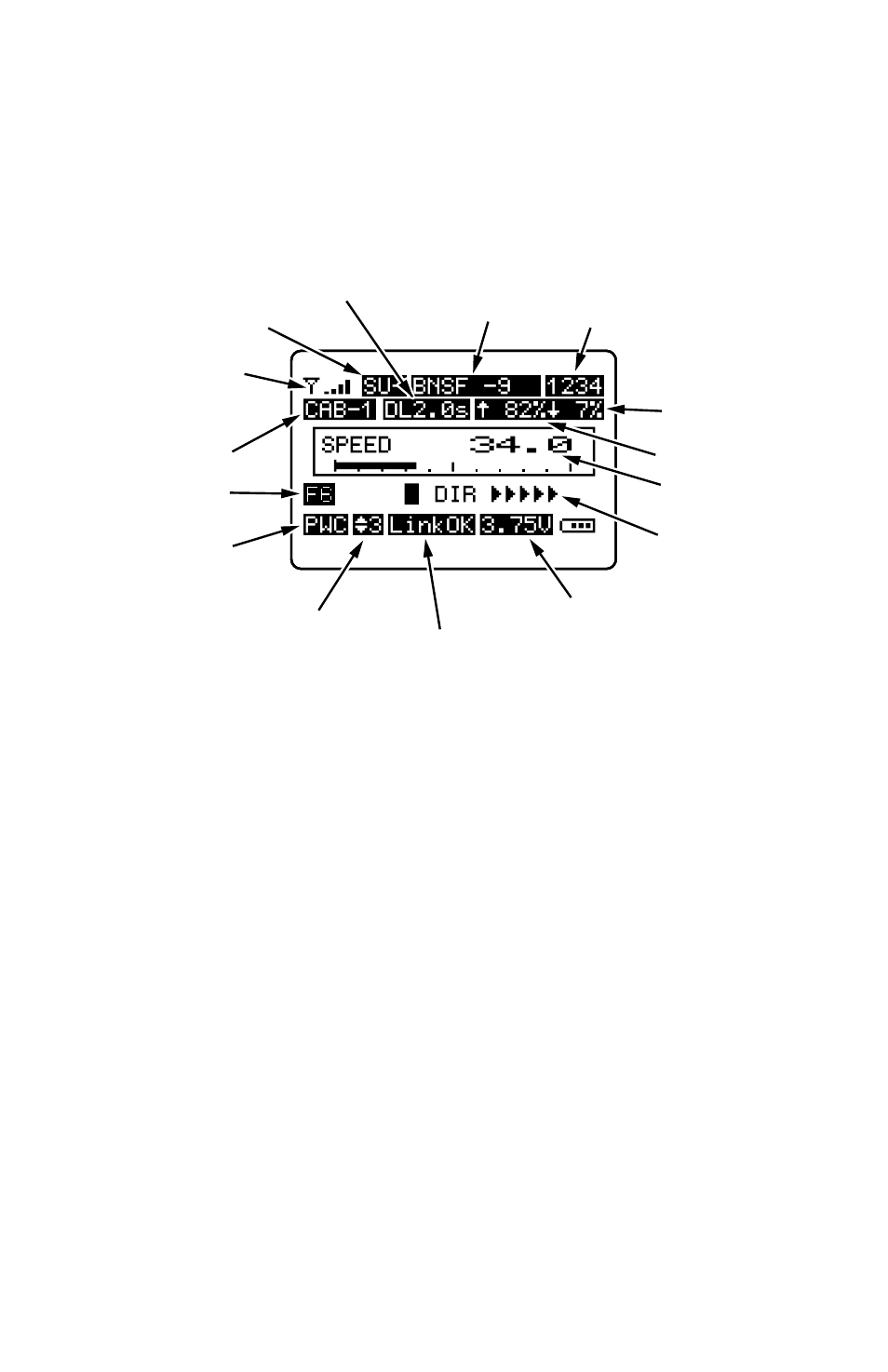
The Transmitter Operating screen
OPERATING SCREEN - First Line
Receiver Signal Strength - The antenna symbol and signal bars, in the upper left
corner of the screen shows the strength of the radio signal between the transmitter
and the locomotive’s receiver. This is reference information only and has no user
setable function.
SU/MU - SU- indicates that the locomotive under control is a single independent
unit. MU2 or MU3 indicates that a Multiple Unit configuration of 2 or more
locomotives is being operated. This is also reference information and it indicates
the selected CAB type.
Loco Name - The active locomotive’s name is programmed by the operator when
programming locomotives
Loco Road Number - The active locomotive’s road number is programmed by the
operator when programming locomotives
OPERATING SCREEN - Second Line
Cab # - The cab number is associated with the locomotive that is being controlled.
This number is programmed by the operator under item 3 of the main menu
ADD MU/SU CAB which is used to assign either single locomotive or multiple
locomotives to a CAB Number for operating purposes. This is what makes MUed
locomotives work as a unit.
RECEIVER
SIGNAL STRENGTH
ACTIVE CAB
PWC/LINEAR
POWER
SPEED STEP
SU/MU
LOCO
NAME
LOCO ROAD
NUMBER
DELAY SETTING
START SPEED
TOP SPEED
CURRENT SPEED
LOCO DIRECTION
TRANSMITTER
BATTERY VOLTAGE
RECEIVER LINK
AUX FUNCTION
FEEDBACK