The serial interface, Rs-232c connector pin assignments, Rs232/c serial interface signals – Compuprint 4247-X03 User Manual
Page 184
Pin Number
Signal Name
Description
16
LOGIC GND
Logic Ground
17
CHASSIS GROUND
Chassis Ground
18
+5 VDC
External Power
19 - 30
GROUND
Ground
31
-INIT
Initialize Printer
32
-ERROR
Printer Error
33
GROUND
Ground
34, 35
Unused
36
-SLCT IN
Make printer selected
The Serial Interface
The 4247 Printer attaches to a host or controller with the RS-232C Serial Interface.
A single 9-pin D-connector mounted directly on the adapter card allows
attachment to the interface.
The RS-232C interface uses a standard serial cable up to 15.2 m (50 ft) in length,
with transmission rates up to 19.2 Kbps.
RS-232C connector pin assignments
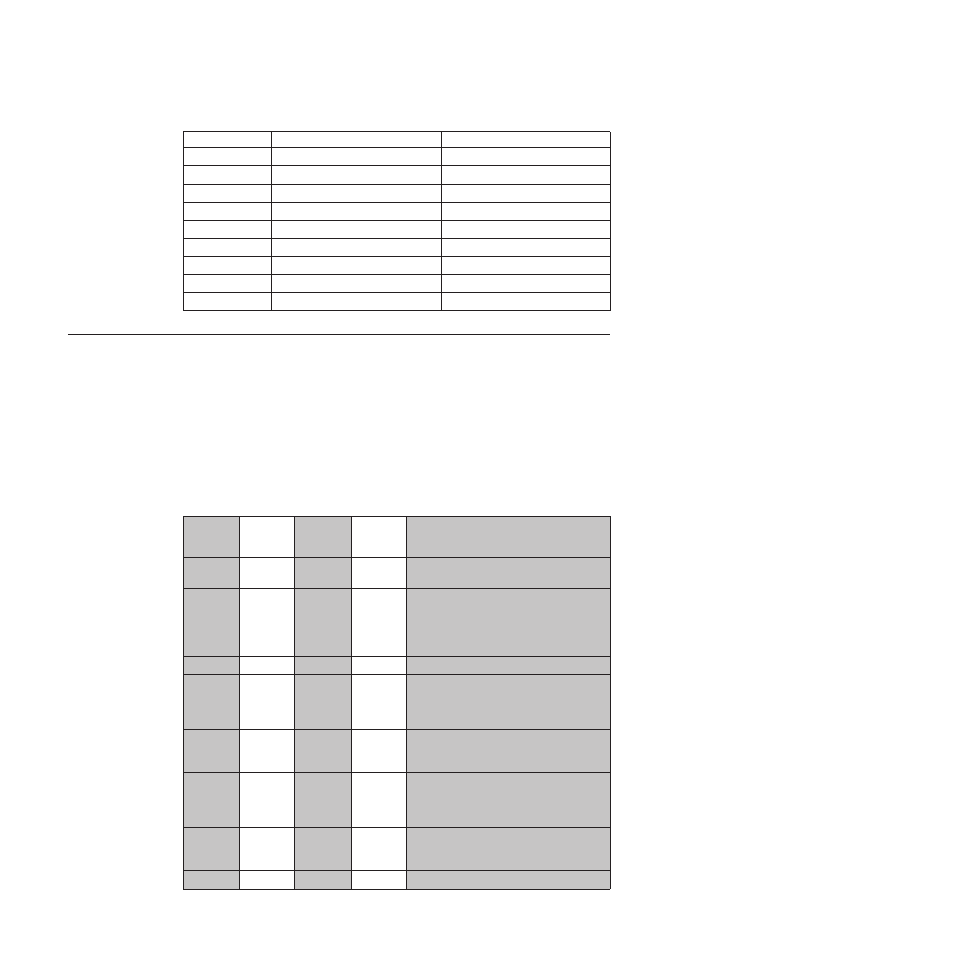
Table 31 lists the RS232/C serial interface signals:
Table 31. RS232/C serial interface signals
Signal
Name
Pin
Number
Local
Connect.
Source
Remote
Connect.
Source
Description
SIGNAL
GROUND
5
–
–
Always connected to the 0 Volts of the
Power Supply
TXD
3
Printer
Printer
Transmitted Data Signal (an output from
printer). A MARK condition is held during
IDLE communication state. An
indeterminate state is present when
printer is powered off.
RXD
2
Host
Data Set
Received data signal (an input to printer).
RTS
7
Printer
Printer
Request to Send Signal (an output from
printer). Active HIGH level signal. It is
HIGH until the printer is powered off,
then an indeterminate state is present .
CTS
8
Data Set
Active HIGH level signal indicates that the
host or data set is ready to receive data
from the printer.
DSR
6
Data Set
Active HIGH level signal. Indicates that
the host or data set is ready to be
connected to the printer and is ready for
data transfer.
DCD
1
Data Set
Active HIGH level signal. Indicates that
the host is transmitting or the data set is
receiving the Data Carrier signal.
2nd RTS
9
Printer
Functionally equivalent to the DTR signal.
168
User’s Guide