Networking principles, Vtx-wm1 installation guide v1.2 7 – Cloud Electronics VTX-WM1 User Manual
Page 7
VTX-WM1 Installation Guide v1.2
7
Networking principles
The VTX-WM1 card communicates with a computer – or the building’s IT system - using standard
IP protocols over Ethernet. Physically, connections are made using CAT-5 cabling (4-pair UTP)
terminated with RJ-45 connectors.
If only one amplifier is to be used, it may be connected directly to a computer (as in Step 11 of
the Installation Procedure), or connected to the IT infrastructure once it has been assigned a
compatible IP address.
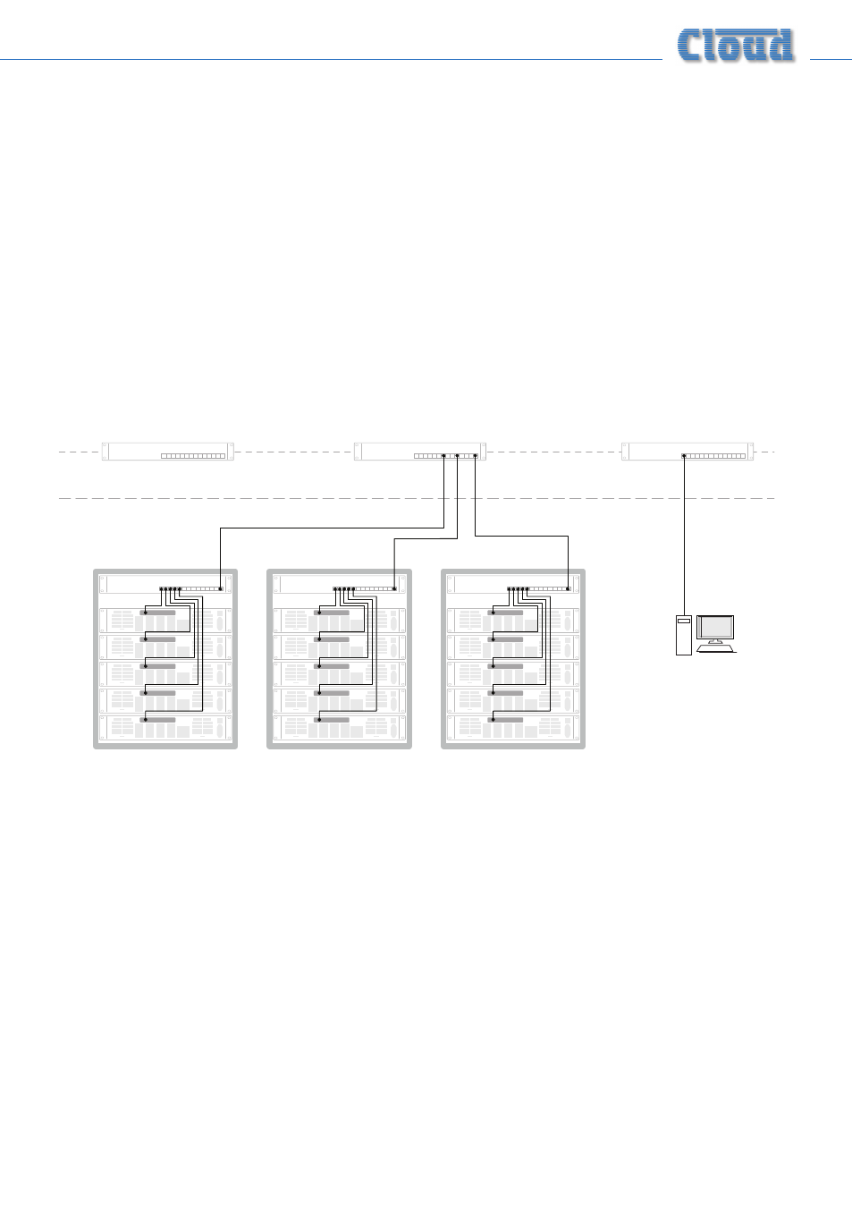
In systems where more than one VTX amplifier is being installed in a rack (or racks), each rack
should ideally* contain an Ethernet switch (10/100baseT or 10/100/1000baseT). This should have a
minimum of (N+2) ports, where N is the number of amplifiers the rack contains. Each amplifier’s
VTX-WM1 card should be connected to a port on the switch, using a standard CAT-5 network
cable. The switch should then be connected into the building’s IT infrastructure at the nearest
convenient point via structured cabling.
SWITCH
SWITCH
SWITCH
VTX #1
VTX #2
VTX #3
VTX #4
VTX #5
SWITCH
VTX #6
VTX #7
VTX #8
VTX #9
VTX #10
SWITCH
VTX #11
VTX #12
VTX #13
VTX #14
VTX #15
RACK 1
RACK 2
RACK 3
FIBRE or CAT5
FIBRE or CAT5
ANY COMPUTER ON
NETWORK
EXISTING BUILDING IT INFRASTRUCTURE
SWITCH
As many amplifiers and racks as required can be networked in this way, and these may, of course,
be anywhere in the building. The only requirement is that each rack switch is connected to
the same building network, so that all amplifiers in the system are accessible from a computer
elsewhere on the network.
* Amplifiers in multiple racks may be wired to a single Ethernet switch in one (adjacent) rack if wished, though this will neces-
sitate a significant amount of additional CAT5 cabling.