Vtx-wm1 installation guide v1.2 6 – Cloud Electronics VTX-WM1 User Manual
Page 6
VTX-WM1 Installation Guide v1.2
6
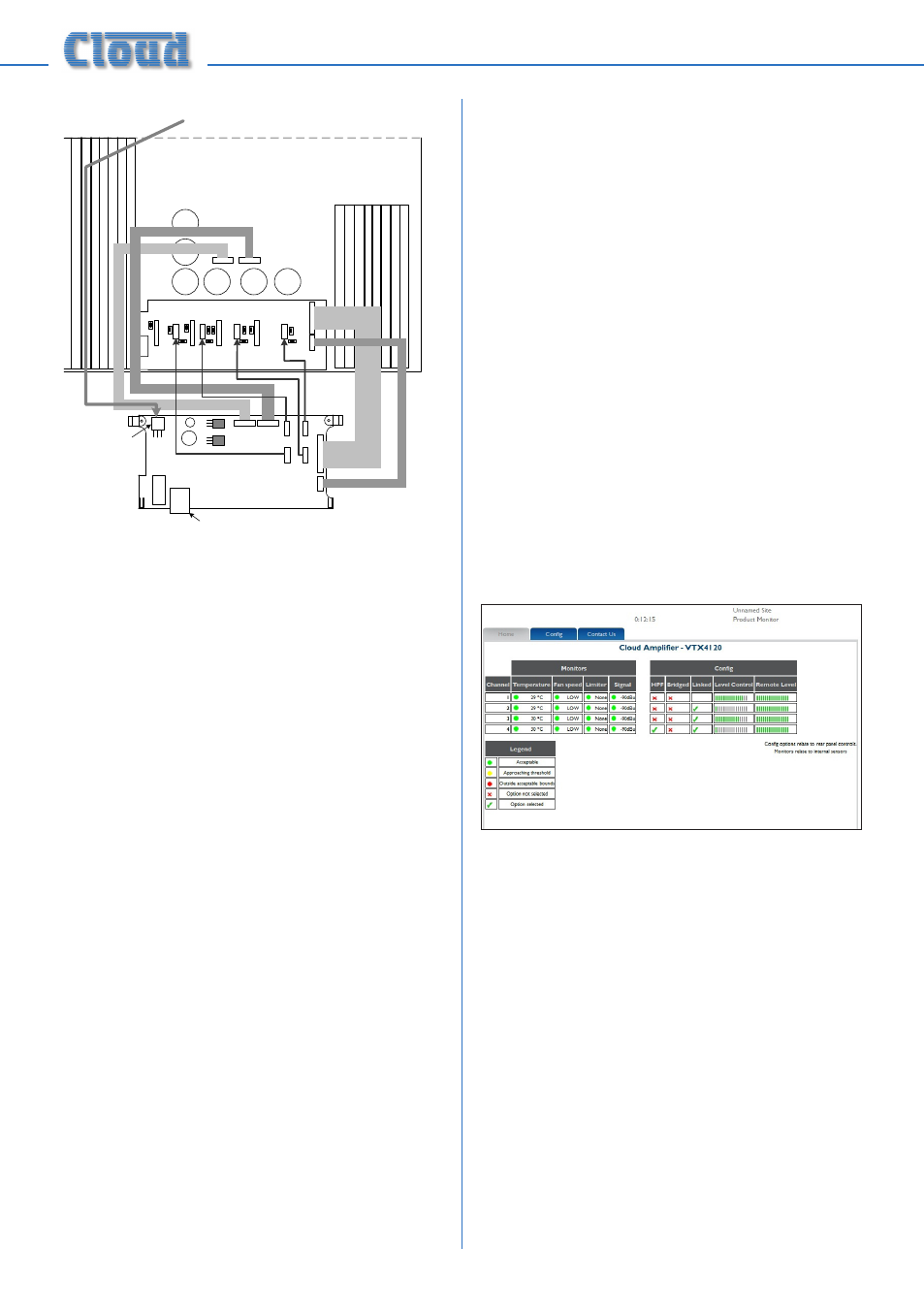
8. The VTX-WM1 card can now be fitted
in place; the two rear supports should
engage with the edge of the heatsinks,
and the RJ-45 Ethernet connector should
protrude through the rear panel slot.
The two previously empty holes in the
amplifier rear panel should align with the
tapped holes in the card’s rear brackets;
secure the card using the two screws
supplied.
9. Locate the spare internal AC cable coming
from the amplifier power transformer. This
will have one red and two yellow wires
and will terminate in a 3-pin Molex plug.
It may be cable-tied; if so, cut the tie. Plug
the connector into the large 3-pin Molex
header on the front left corner of the
VTX-WM1 card.
10. Fix the new rear plate (supplied) over the
card slot using the two screws removed
in Step 3, so that the RJ-45 connector is
engaged with the square hole in the plate.
Replace the top cover.
11. We recommend that the amplifier is
connected to a computer at this stage
to check communications. Connect the
VTX-WM1 card’s Ethernet port to the
network port on a computer using a
standard CAT5 (or CAT5-e) network
cable, terminated with RJ45 plugs. Either
a “straight” or a “crossed” cable may be
used, as the VTX-WM1 auto-detects the
data lines. Power the amplifier on; it is
not necessary at this stage to connect
any audio inputs or outputs. Turn the
computer on and check that it has a static
IP address of the form 192.168.0.xxx,
where xxx can be any value between
1 and 254 except 127. Launch the Internet
browser normally used (e.g., Microsoft
Internet Explorer, Mozilla Firefox, Safari,
etc.)
12. Type the card’s default IP address -
192.168.0.127 - into the URL field of the
browser, and the screen shown below
should appear:
The amplifier type listed in the title
should be that of the amplifier in use. This
confirms that the data communications
section of the card is operating correctly.
The card’s IP address can be changed
subsequently, and this procedure is
discussed in “Entering site and amplifier
information” on page 8.
13. Close the browser application. The
amplifier may now be disconnected from
the computer and powered off. Reinstall in
the rack and reconnect all rear cables.
14. Repeat the above procedure for the
remaining VTX amplifiers.
POWER
CONNECTOR