Amplifier data – using the gui, Monitors, Configuration – Cloud Electronics VTX-WM1 User Manual
Page 10
VTX-WM1 Installation Guide v1.2
10
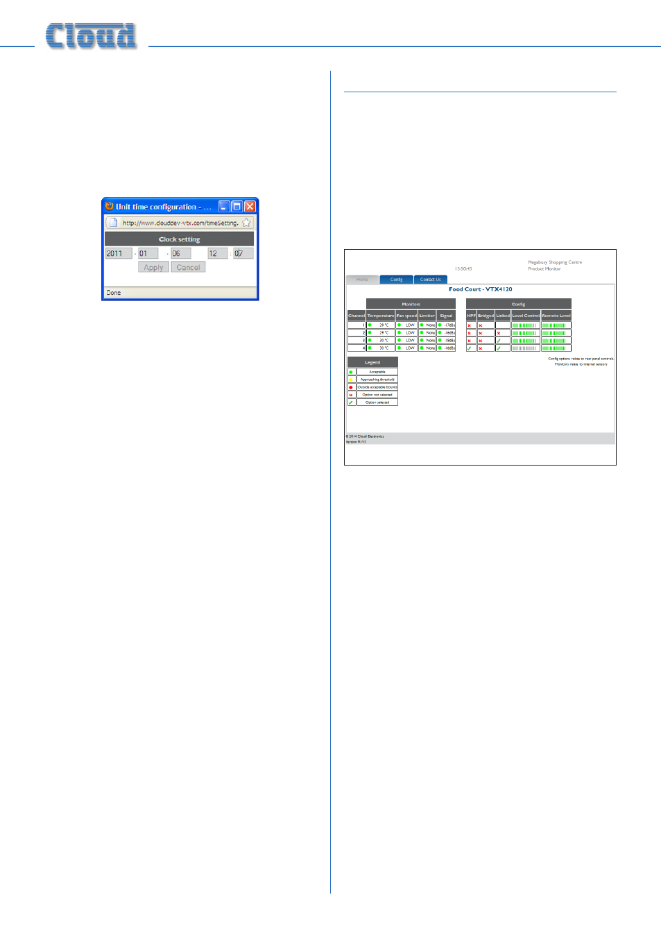
13. The VTX-WM1 card has an on-board
clock/calendar, which needs to be set
for the Event Log to be meaningful. The
default
Current Time will be midnight
on Jan. 1
st
. 2000; click the adjacent
Set
button to open the
Clock setting
window.
Enter the current date and time in the five
fields in the format yyyy-mm-dd hh:mm
and click
Apply.
14. Click
Apply on the Amplifier
Properties page to confirm the data
entered.
15. Enter the amplifier’s new IP address into
the browser’s URL field to re-establish
communication with the card. The
Home
page will now confirm the Site and
Amplifier Names which were entered.
16. Repeat the procedure for each amplifier
to be connected. Note each time, that the
PC may take a few moments to recognise
that a VTX-WM1 card has had its address
changed; this is normal.
17. When all the amplifiers have been
configured, the Ethernet switch may be
reconnected to the building’s IT network.
It is recommended that access to the
amplifiers is re-checked by entering each
IP address on a computer elsewhere on
the network.
Amplifier data – using the GUI
Once the amplifiers have been configured,
amplifier performance and settings can be
monitored from the web browser of any
computer on the network. To access an
amplifier, enter the IP address of the amplifier
to be viewed into the URL field of the web
browser. This will show the
Home Page, an
example of which is shown below:
The
Home Page gives a overview of the
amplifier.
Each channel of the amplifier reports its status
as follows:
Monitors:
•
Internal heatsink temperature
•
Fan speed
•
Clip limiter circuitry status
•
Input signal level (in dBu)
Configuration:
•
High-pass filter – rear panel switch setting
•
Bridge mode – rear panel switch setting
•
Input linking – rear panel switch setting
•
Current level control – rear panel rotary
control setting
•
Current external level control – RL-1
remote control plate setting (if fitted)