Installation instructions, Pcb layout diagrams, The ma60 and ma60 – Cloud Electronics MA60Media User Manual
Page 30: Ma60 & ma60, Installation and user guide v1.2, Media
MA60 & MA60
media
Installation and User Guide v1.2
30
Installation Instructions
Refer to the PCB layout diagram (see “PCB layout diagrams” on page 30) for the
location of the EQ module connector and its associated bypass jumper J8.
To install an EQ module, proceed as follows:
1. Switch off the power and isolate the unit from the mains.
2. Remove the top panel.
3. Move jumper J8 on the main PCB from ‘ON’ to ‘OFF’.
4. Plug the loudspeaker equalisation module into its 12-pin connector CN16; note
that the connector has two notches on one side which engage with lugs on the
module’s mating connector to ensure correct orientation.
5. Replace the top panel.
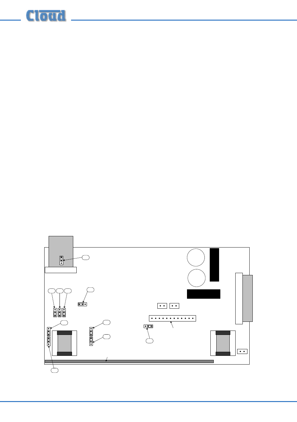
PCB layout diagrams
The MA60 and MA60
media
have two PCBs which are fitted with jumpers, the Main
PCB and the Input PCB. With the top cover removed from the unit, and the rear
connector panel towards you, the Main PCB is fitted to the base at the rear of the
chassis, while the Input PCB is mounted vertically on the Main PCB immediately
behind the rear panel, and carries most of the connectors and controls.
The diagrams below indicate the locations of the various jumpers, and also the EQ
card socket. They are for guidance only and are not to scale.
CN16
J1
J5
J14
J15
J2
J3
J4
J7
J8
J13
(below ribbon cable)
Loudspeaker EQ card socket
Input PCB (vertically-mounted)
MA60 MAIN PCB
VIEW FROM REAR
NOT TO SCALE - Only primary components shown
ON
O
FF
ON
OF
F
SW
AVO
NC
NO
ON
O
FF
ON
OFF
ON
OFF
ON OFF
CN15A
CN15B
Lo-Z outputs