Ma60 & ma60, Installation and user guide v1.2 – Cloud Electronics MA60Media User Manual
Page 22
MA60 & MA60
media
Installation and User Guide v1.2
22
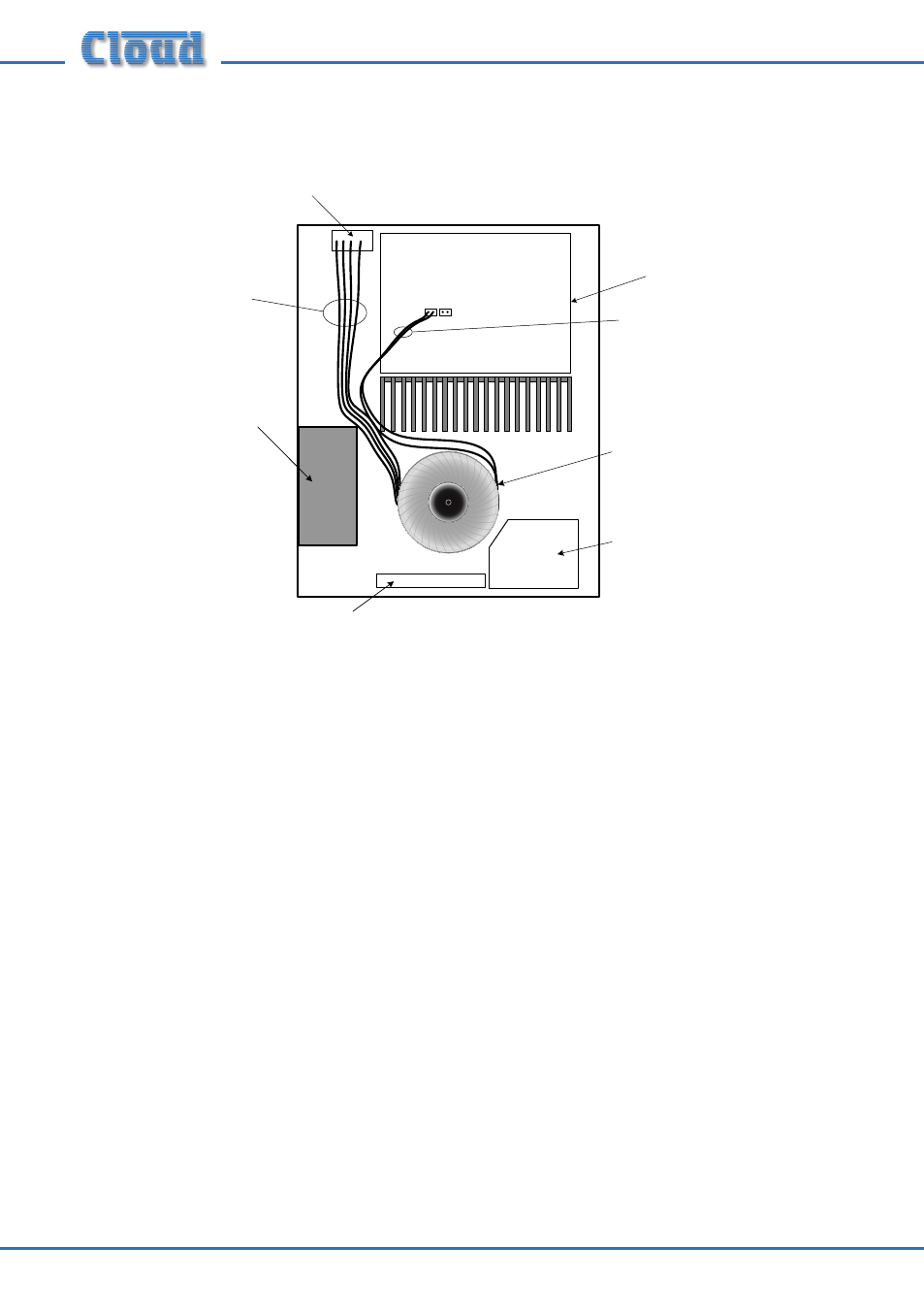
FRONT PANEL
MEDIA
PLAYER PCB
FRONT PANEL
CONTROLS PCB
MAINS
TRANSFORMER
CXL-50T OUTPUT
TRANSFORMER
MAIN PCB
CN15A
CN15B
100/70/50 V-LINE OUTPUT
CONNECTOR PCB
Red/Brown/
Blue/Black
White/Black
5. The primary winding of the transformer is terminated in a two-pin Molex-type
connector. This should be plugged into the header marked CN15B on the
main PCB. See “PCB layout diagrams” on page 30 for location.
6. On the rear panel, remove the plastic blanking plate covering the LINE
OUTPUT connector hole.
7. Fit the 4-pin connector on the ends of the secondary winding leads from the
transformer (the remaining four) into this hole, so that the threaded holes
in the two PCB mounting brackets line up with the two holes alongside the
connector. Use the male ends of the hex pillars (supplied) to secure the PCB
and connector in place.
8. Use the two cable ties supplied to tidy up the transformer leads; ensure that
they do not pass over the top of the main heat sink.
9. Replace the top cover, using the original screws.
10. Connect the speaker system to the line outputs using the mating connector.
Note that only two of the pins will be used; one will always be pin 1 (0 V).