Ext standby input, The ma60/ma60 – Cloud Electronics MA60Media User Manual
Page 26
MA60 & MA60
media
Installation and User Guide v1.2
26
connector on the rear panel. The input is usually connected to a pair of isolated relay
contacts activated by the fire system.
Note that the Music Mute function only mutes the MA60/MA60
media
’s main output;
the MOH/Utility output remains active.
When Music Mute is activated, the front panel MUTE LED
6
illuminates to confirm
that the resulting silence is due to an external Music Mute command.
Activation of the Music Mute is often via a relay mounted close to the MA60/
MA60
media
and any associated equipment, powered by the fire alarm control panel.
Other arrangements may exist depending on the design of the fire control system
and the fire alarm installation company should be consulted when making the
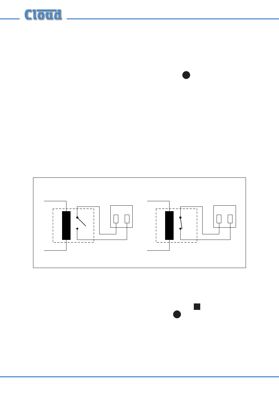
connection. The MA60/MA60
media
will mute on either a contact closure at the Music
Mute input (NO) or an open circuit (NC). Selection of NO or NC operation is made
with internal jumper J15. NO is the factory default. See “PCB layout diagrams” on
page 30 for further information regarding the internal jumpers. The diagram below
shows the two connections.
Ext Standby Input
The MA60/MA60
media
may be remotely switched in and out of AC power standby
mode by connecting the rear panel EXT STANDBY connector
17
to an external
5 V DC source. Providing the front panel power switch
1
remains on, 5 V DC
applied across the terminals will cause the MA60/MA60
media
to to go into standby
mode. The 5 V source used should be able to supply 40 mA. This is a useful feature as
it permits the unit to be powered on and off from a system controller, for example.