Bypassing transformers in the 46-120t and 46-120t, Media, Fitting the eq security cover – Cloud Electronics 46-120TMedia User Manual
Page 29
46-120 Installation and User Guide V1.2
29
5. Identify the first transformer’s primary winding – this is
the red/black flying lead fitted with a male connector. Plug
the female connector removed in Step 4 into this. Note
the pin and latch orientation – the connectors will only
mate one way.
6. If configuring the zone output for 100 V-line operation,
plug the transformer’s secondary winding – the other
flying lead (blue/mauve/white) - into the second
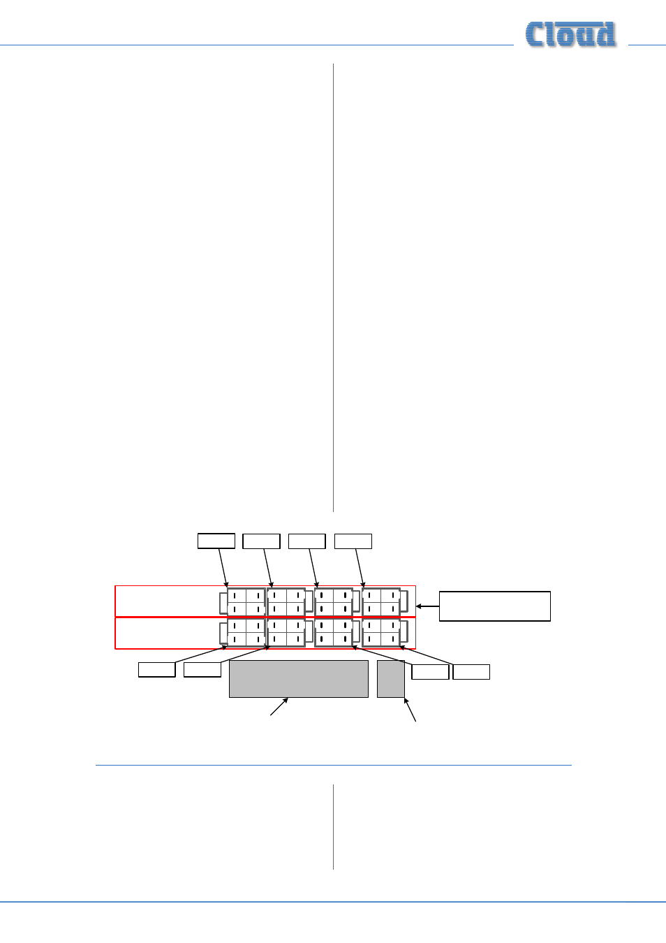
ZONE
O/P socket; this will be the one paired with the socket
unplugged in Step 4, and closer to the
SPEAKER
OUTPUTS connector. These are: CON43 (Zone
1), CON44 (Zone 2), CON45 (Zone 3) and CON46
(Zone 4). Note that CON43 is orientated at 180° relative
to the other three. See diagram below.
7. If configuring the zone output for 70 V-line operation,
plug the transformer’s other flying lead (blue/mauve/
white) into the
ZONE O/P connector vacated in Step 4.
8. For each zone being converted to 100/70 V-line operation,
enable the channel’s 65 Hz hi-pass filter by moving
the appropriate jumper from OFF to ON: these are J3
(Zone 1), J4 (Zone 2), J8 (Zone 3) and J9 (Zone 4). See
page 30 for location of PCB jumpers.
9. Repeat Steps 3 to 8 for the other zones being converted.
10. Replace the cover.
Bypassing transformers in the 46-120T
and 46-120T
MEDIA
It may occasionally be necessary to revert one or more zone
outputs of a 46-120T or 46-120T
MEDIA
to low-impedance
operation. In this case, follow the procedure below:
1. Disconnect the 46-120 from the mains.
2. Remove the top cover (10 screws) and orient the unit
with the rear panel towards you.
3. For the first zone being converted to low impedance
operation, unplug the 4-pin female transformer secondary
connector from its
ZONE O/P socket on the main
PCB immediately behind the rear panel
SPEAKER
OUTPUTS connector. See diagram below.
4. Unplug the transformer’s 4-pin male primary winding
connector from the zone output flying lead. Check it is
for the correct zone - see table on page 28 for colour
coding.
5. Plug the zone output flying lead into the
ZONE
O/P socket in the row further from the SPEAKER
OUTPUTS connector These are: CON38 (Zone
1), CON39 (Zone 2), CON40 (Zone 3) and CON41
(Zone 4). See diagram below.
6. For each zone being reverted to low impedance
operation, disable the channel’s 65 Hz hi-pass filter by
moving the appropriate jumper from ON to OFF: these
are J3 (Zone 1), J4 (Zone 2), J8 (Zone 3) and J9 (Zone 4).
See page 30 for location of PCB jumpers.
7. Repeat for the other zones being converted.
8. Replace the cover.
ZONE 1 O/P
ZONE 4 O/P
ZONE 3 O/P
ZONE 2 O/P
SPEAKER OUTPUTS
connector
REMOTE POWER DOWN
connector
PLUG TRANSFORMER
SECONDARY IN HERE FOR
100 V OPERATION
PLUG TRANSFORMER
SECONDARY IN HERE FOR
70 V OPERATION
THESE CONNECTORS ARE
ALSO USED FOR LO-Z
OPERATION
CON38
CON46
CON45
CON44
CON43
CON41
CON40
CON39
Fitting the EQ security cover
A security cover is supplied with the 46-120 which can be
fitted to the front panel to prevent access to the Zone EQ
preset controls. The
MIC LEVEL, MUSIC LEVEL and
MUSIC SOURCE controls remain accessible and the CLIP
LED is still visible.
The panel is simply placed over the rotary control knobs
and secured in place with the four M3 x 6 hex-head screws
supplied.