Paging system connections – Cloud Electronics 46-120TMedia User Manual
Page 16
46-120 Installation and User Guide V1.2
16
in the vast majority of installations there will be no power
supply issues. See page 32 for more information about the
46-120’s DC power
capabilities.
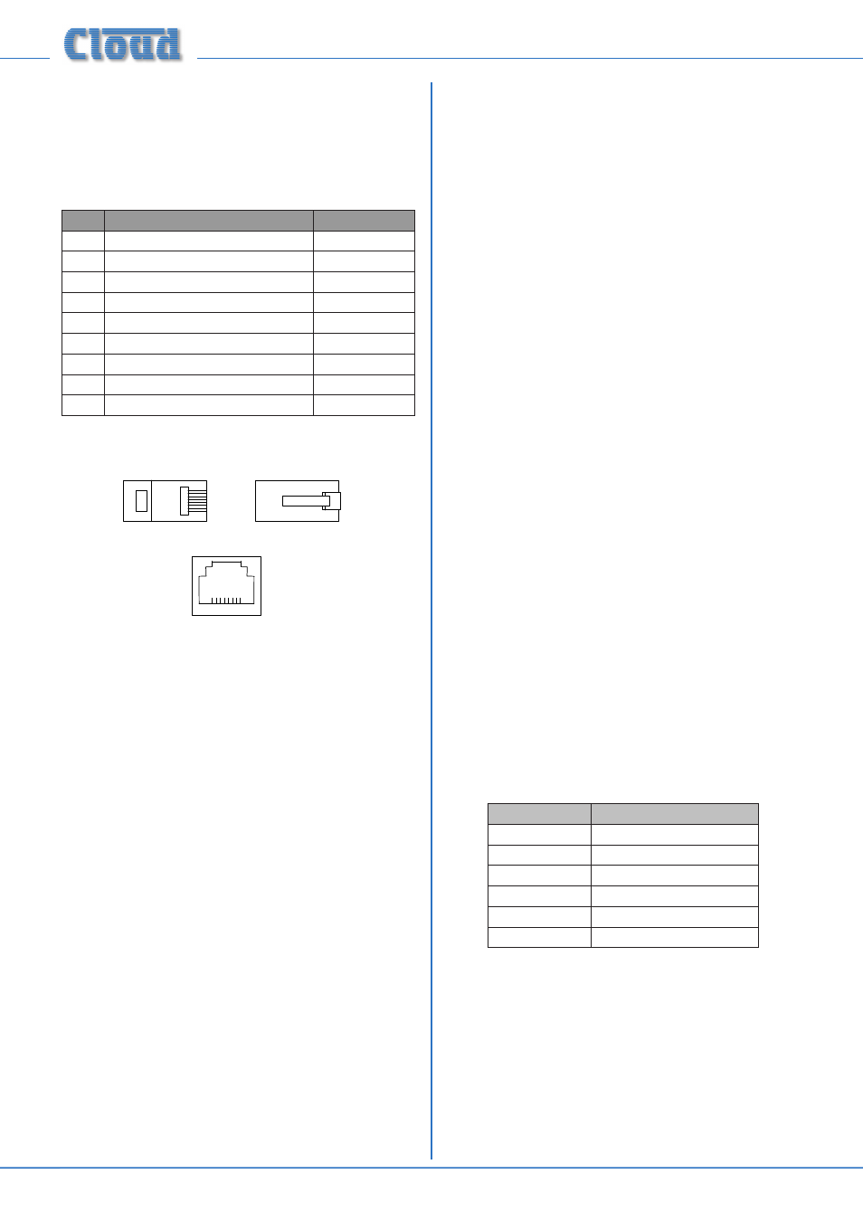
The pinout of the Facility Port connector is given in the table
below:
PIN
USE
Cat 5 CORE*
1
Audio ‘cold’ phase (-)
White + Orange
2
Audio ‘hot’ phase (+)
Orange
3
Priority VCA control
White + Green
4
+ 15 V
Blue
5
0 V
White + Blue
6
-15 V
Green
7
Music level control (0 to 10 V)
White + Brown
8
Music source select control (0 to 10 V)
Brown
SCN
Screen for system music controls
Connector shell
* Standard wiring for pre-made cables
Please also refer to page 26 for further information
regarding installation of remote active input modules.
Connecting an LM-2 remote active module
The LM-2 should be connected to the
FACILITY PORT
using screened Cat 5 cable. (Note that as the cable carries
analogue audio, only screened Cat 5 should be used.) All eight
cores are used. The LM-2 includes controls for local music
level and source selection, the wiring for these functions being
catered for on the Facility Port; thus it is not necessary to
make any connections to Zone 1’s
MUSIC CONTROL
port.
The LM-2’s upper PCB is fitted with an RJ45 connector
labelled
OUTPUT. Connect this to the FACILITY PORT
of the relevant Zone using screened Cat 5 cable with screened
RJ45s at each end. Follow the colour coding shown in the
table above. The metal screening of the connectors should be
bonded to the screen of the cable. Full details can be found in
the LM-2 Installation Guide.
The second RJ45 connector on the LM-2,
LINK, may be used
to “daisy-chain” additional LM-2s, thus allowing multiple input
modules to be installed at different locations in the Zone. See
the LM-2 Installation Guide for more details.
Before the LM-2’s music source and level controls will operate,
set the Zone 1
MUSIC CONTROL LEV and SRC push-
button switches ([10] on page 12) to REMOTE (i.e., pressing
it in). In this setting, Zone 1’s front panel
MUSIC LEVEL and
MUSIC SOURCE controls become inoperative. Sometimes
it is desirable to permit remote control of music level but
retain music source selection at the mixer amplifier. In this
case, set only the
LEV switch to REMOTE. This will render
the LM-2’s music source switch inoperative, and return source
selection to the 46-120’s front panel.
Paging system connections
Cloud PM Series paging microphones may be connected
directly to the 46-120 in two ways:
• via the Cloud Digital Paging interface ([20] at page 12)
– only available if the CDI-46 Digital Interface card is
fitted.
• using the
MIC 1/TEL input and ACCESS CONTACTS
connector.
Connecting PM4/4SA paging microphones
Cloud PM Series microphones are available in 4, 8, 12 or 16-
zone versions; the installer should be sure he/she understands
how paging zones correspond to mixer zones before
commencing wiring. Although the 46-120 only supports
a maximum of four zones, there is no technical reason to
prevent a PM microphone being used in a restricted manner.
Connection via the CDPM/PM port:
If a CDI-46 Digital Interface card is fitted, the PM4 may be
simply connected to the
CDPM/PM INPUT using screened
Cat 5 cable. No other connections are required; a PM4 will
be powered from the 46-120, but a PM4-SA will require an
external PSU. Full installation instructions are supplied with
the PM Series microphone and the CDI-46 card.
Connection via the Mic input
Two connections are required: the paging mic audio signal
should be connected to the
MIC 1/TEL input ([4] on page
12) and the control cable to the 6-pin Zone
ACCESS
CONTACTS port ([8] on page 12). The pinout of the
ACCESS CONTACTS port is given below:
PIN NO.
FUNCTION
1
0 V
2
Zone 1
3
Zone 2
4
Zone 3
5
Zone 4
6
+12 V
Standard two-core screened audio cable should be used for
the audio signal, and stranded multicore cable with an overall
screen for the control cable.
Connections on the PM microphone are made via the
rear cable access glands and screw terminal blocks on the
internal PCB (
TERM1, TERM2 and TERM8 in the case of
a PM4). Full connection details can be found in the PM Series
Installation and User Guide.