Music control, Connecting a pm1 paging microphone, Connecting oem paging microphones – Cloud Electronics 46-120TMedia User Manual
Page 17
46-120 Installation and User Guide V1.2
17
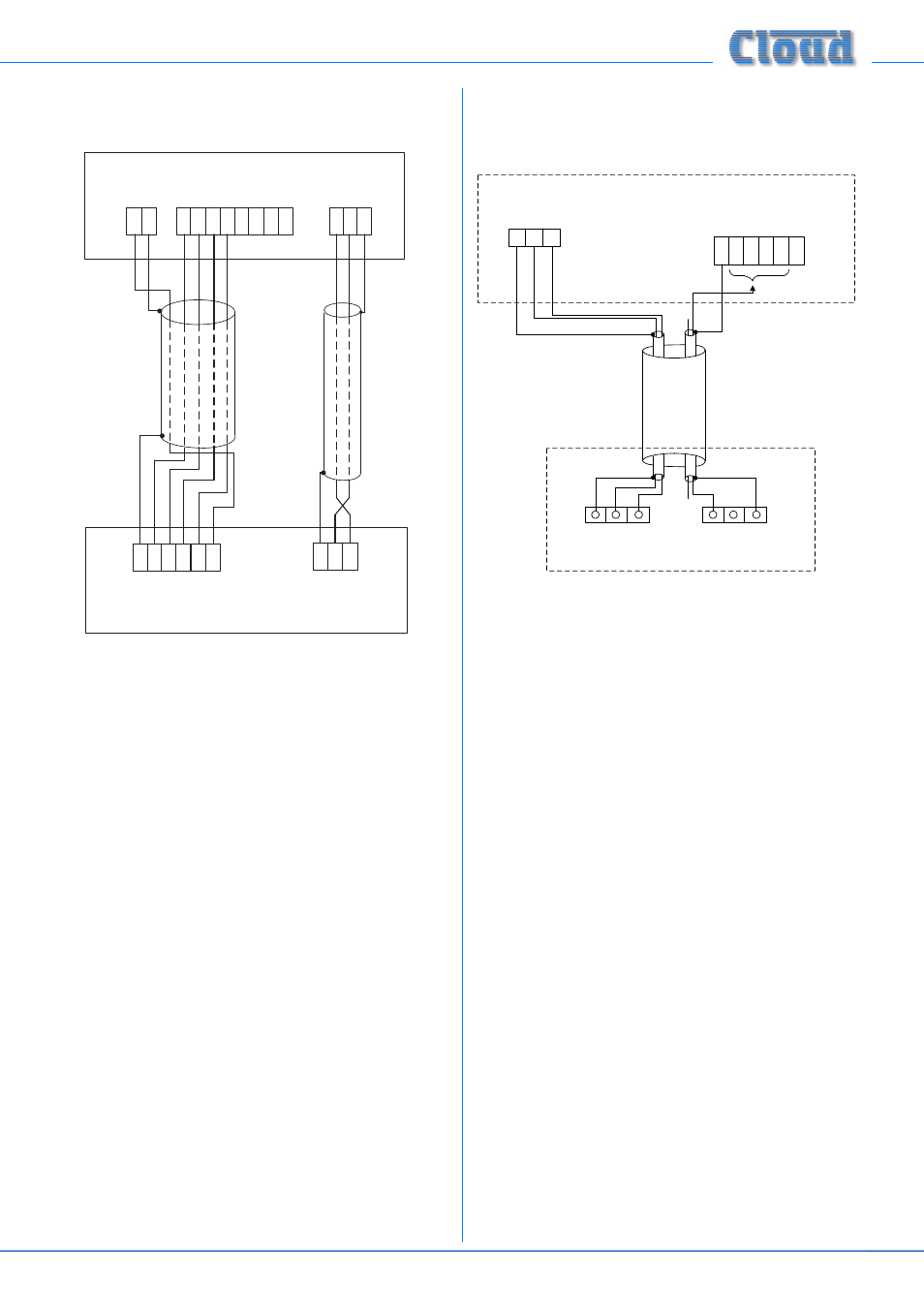
The diagram below shows the cable connections between a
PM4 and a 46-120
.
TERM8
TERM2
HOT COLDGND
Z1
Z2
Z3
Z4
MIC 1/TEL INPUT
Z1
Z2
Z3
0 V
PM4 PAGING MICROPHONE
46-120
Z5
Z6
Z7
Z8
TERM1
0V
+V
+V
Z4
1
3
2
ACCESS CONTACTS
Note that the default factory setting is for all
ACCESS
CONTACTS port inputs to be permanently enabled. In
order for the 46-120’s mic input to function correctly with
a paging mic, internal jumpers J10 to J13 (Zones 1 to 4
respectively) should be removed. See page 30 for jumper
locations.
For automatic music ducking during an announcement, the
internal jumper J6 should be set to ON (its factory default
setting). See page 24 for further information.
Connecting a PM1 paging microphone
The PM 1 is a simple, passive paging microphone suitable for
situations where announcements are always made to the
same zone(s). It can be connected directly to the 46-120
Mixer Amplifier, the control cable being wired to the pin(s)
of the
ACCESS CONTACTS connector corresponding
to the zone(s) in which announcements are required. Any or
all of the zones may be paralleled if multiple zones need to
operate from the PM1.
Either a single 2-pair individually-screened cable may be
used (this gives the neatest finish), or two separate standard
microphone cables. Connections on the PM1 are made via the
rear cable gland in the base and the screw terminal blocks on
the internal PCB (U2 and U3). Full connection details can be
found in the PM1 Installation and User Guide. Note that the
PM1 does not require DC power.
The following diagram shows the connections between a PM1
and a 46-120. Use of 2-pair cable is assumed; the same wiring
principle is adopted if separate cables are being used for audio
and control.
PAGING MIC INPUT
SCN COLD HOT
N/O N/C GND
U2 AUDIO
U3 ACCESS
ZONE ACCESS CONNECTOR
CONNECT TO
ZONE(S) IN USE
1 2 3
0V Z1 Z2 Z3 Z4 +V
46-120
PM1
Note that the default factory setting is for all
ACCESS
CONTACTS port inputs to be permanently enabled. In
order for the 46-120’s mic input to function correctly with
a paging mic, internal jumpers J10 to J13 (Zones 1 to 4
respectively) should be removed. See page 30 for jumper
locations.
For automatic music ducking during an announcement, the
internal jumper J6 should be set to ON (its factory default
setting). See page 24 for further information.
Connecting OEM paging microphones
Other manufacturers’ paging microphones may be used
with the 46-120, provided they make the microphone signal
available at a suitable level (the 46-120’s mic gain adjustment
range should be sufficient to accommodate most types), and
that paging zone selection is by simple “contact closure-to-
ground”. Providing these conditions are met, the connection
method described above for a Cloud PM4 using the Mic Input/
Access port method, or for the PM1 in the case of a single-
zone mic, may be used.
Music control
Like many other Cloud products, the 46-120 allows remote
control of music level and source selection in each zone.
Cloud remote control plates from the RL-1 Series (music
level only) and RSL-6 Series (music level and source selection)
provide an elegant solution, though control via a DC voltage
from third-party systems is also possible (see page 26).
Both types of plate connect via the
MUSIC CONTROL
port for the relevant zone (see [9] on page 12). Each zone
uses a 3-pin 5 mm-pitch screw terminal type connector. Please
refer to page 26 for additional information.