Fitting loudspeaker eq cards, Fitting cxl-46t transformers – Cloud Electronics 46-120TMedia User Manual
Page 28
46-120 Installation and User Guide V1.2
28
8. Fix the card in place: use the four M3 x 6 screws supplied
to secure the rear to the hex pillars and the connector
end to the 46-120 rear panel.
9. Plug the 20-way ribbon cable from CON4 on the card
into CON13 on the line input sub-board.
10. Plug the ribbon cable removed in Step 3 into CON6 on
the card.
11. Plug the 10-way ribbon cable from CON8 on the card
into header CON21 on the main PCB.
12. Plug the 20-way ribbon cable from CON7 on the card
into header CON22 on the main PCB.
13. Plug the 10-way ribbon cable from CON5 on the card
into header CON23 on the main PCB.
14. Replace the top cover using the same screws (Step 2).
Fitting loudspeaker EQ cards
The 46-120 is compatible with various popular installed-
sound loudspeakers; a single-channel loudspeaker equalisation
module may be fitted to any or all of the four zone outputs as
required, to optimise the frequency response of the channel
to the loudspeaker type being used.
The cards may be obtained from Cloud Electronics as
optional accessories. Please check the Cloud website
for makes and models of loudspeakers
for which compatible EQ cards are available.
To install equalisation modules, first remove the top cover
from the 46-120 (10 screws). The modules plug into the
white 12-pin connectors labelled CON19 (Zone 1), CON9
(Zone 2), CON17 (Zone 3) and CON8 (Zone 4) on the
main PCB. Note the header connectors on the PCB have
two notches on one side only; these engage with lugs on the
equalisation module’s mating connector to ensure correct
orientation.
See the Appendix section “PCB jumper locations and settings”
page 30 for further details. Replace the top cover with the
original screws after fitting.
Fitting CXL-46T transformers
CXL-46T transformers allow the 46-120 and 46-120
MEDIA
to
be used with 100/70 V-line loudspeaker systems. They may be
fitted to any or all of the four zone outputs. (Models 46-120T
and 46-120T
MEDIA
will have four CXL-46Ts pre-fitted at the
factory, connected for 100 V-line operation (70V-line, US only).
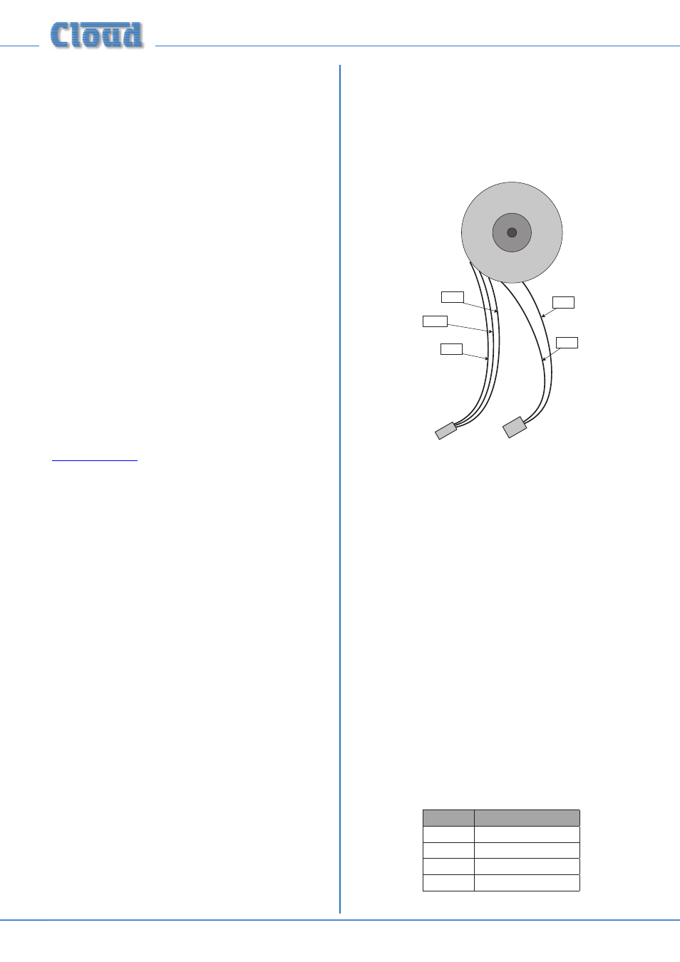
The transformer connections are as shown below:
RED
BLACK
PRIMARY
WINDING
CONNECTOR
(male)
SECONDARY
WINDING
CONNECTOR
(female)
WHITE
BLUE
MAUVE
To fit CXL-46T transformers, proceed as follows:
1. Disconnect the 46-120 from the mains.
2. Remove the top cover (10 screws) and orient the unit
with the rear panel towards you.
3. Mount the CXL-46T transformer(s) on the right-hand
side of the 46-120 chassis, using the holes in the side of
the chassis and the M5 x 40 screw, washer and locknut
supplied with each transformer. The bolt passes through
the centre of the toroid, and the screw head should be
on the outside of the chassis. If fitting fewer than four
CXL-46Ts, any of the fixing positions may be used. Orient
the transformers so that the flying leads face the rear of
the chassis.
4. For the first zone being converted to 100/70 V-line
operation, unplug the 4-pin female connector from the
ZONE O/P sockets on the main PCB immediately behind
the rear panel
SPEAKER OUTPUTS connector. These
are: CON38 (Zone 1), CON39 (Zone 2), CON40 (Zone
3) and CON41 (Zone 4) - see diagram below. Note that
CON38 is orientated at 180° relative to the other three.
The wires on these connectors are colour-coded to aid
zone identification:
ZONE
OUTPUT WIRING
1
Red & Black
2
Orange & Black
3
Yellow & Black
4
Purple & Black