Fitting the cdi-46 digital interface, Control of music source and level via external dc, Music level – Cloud Electronics 46-120TMedia User Manual
Page 27: Music source
46-120 Installation and User Guide V1.2
27
Control of music source and level via
external DC
It may be necessary in some installations to adjust the music
level and select music source in one or more zones from
an external control system (e.g., Crestron, AMX, etc.) If the
MUSIC CONTROL ports are not required for RL-1/RSL-6
Series remote control plates, they may be used to receive DC
voltages from the external system to effect these adjustments.
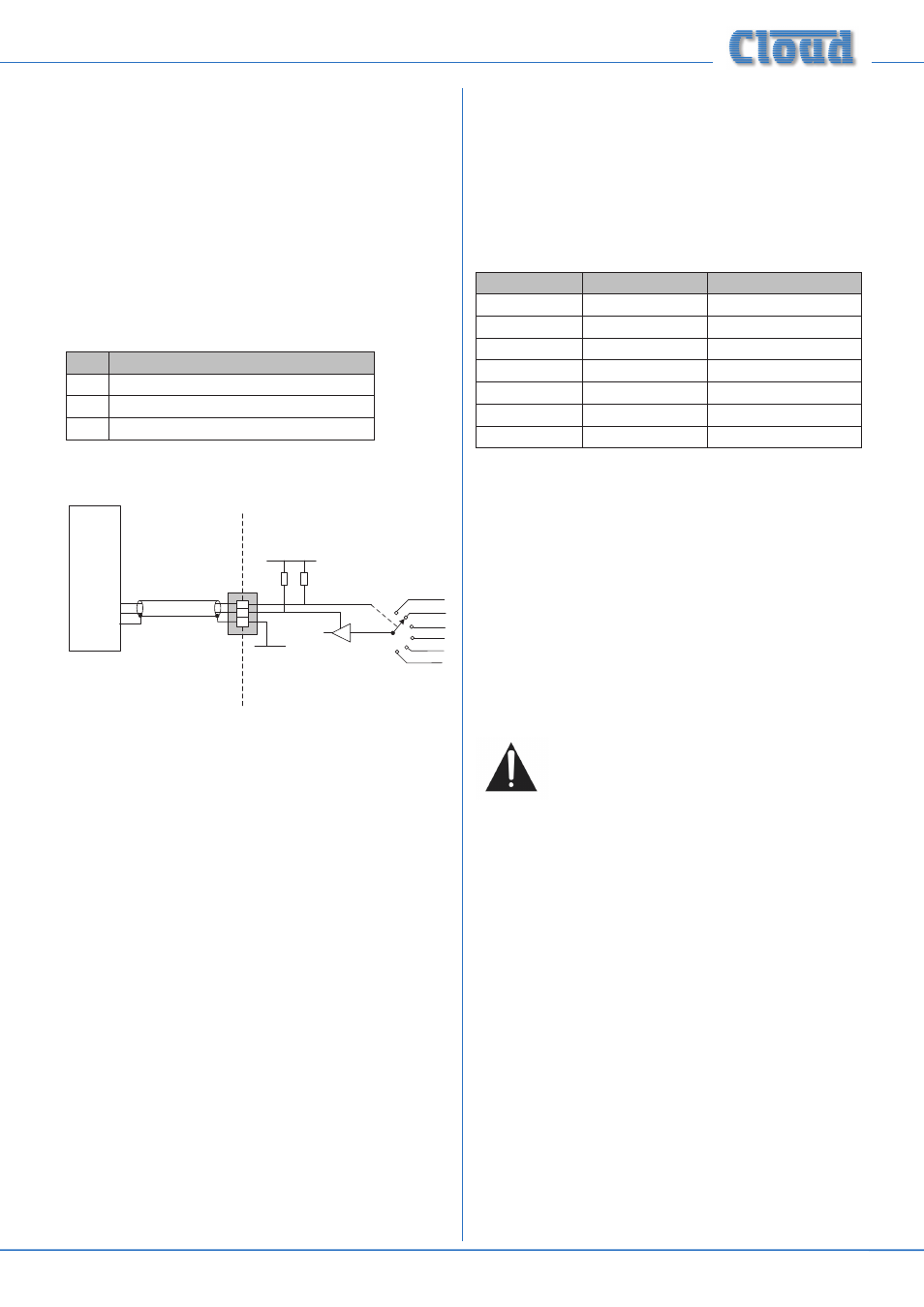
Both music source selection and level can be controlled over
their full ranges with a DC voltage of 0 to +10 V. The pinout
of the
MUSIC CONTROL port is as follows:
PIN
USE
1
0 V ref.
2
Music level control (0 to +10 V)
3
Music source selection (0 to +10 V)
REMOTE
SOURCE+LEVEL
PORT
1
2
3
+15 V
0 V
MUSIC VCA
MUSIC SOURCE
SELECT
4k7
15k
CONTROL
SYSTEM
0 V REF
LEVEL CONTROL
SOURCE CONTROL
42-120
NOTE: If the control voltage source is not isolated from
the power earth, there is a small risk of creating a ‘ground
loop’ by linking the mixing amplifier technical ground (0 V)
to the ground (0 V) of the equipment supplying the control
voltages. To minimise this risk, we suggest that all pieces of
equipment be in close proximity, and supplied from the same
power outlet.
Music level
Music level in a zone may be varied over its full range by
applying a DC voltage of between 0 and +10 V to pin 2, the 0 V
reference being connected to Pin 1. 0 V on pin 2 corresponds
to maximum level and +10 V will produce 60 dB of attenuation.
The rate of attenuation is approximately 165 mV/dB.
Note that there is an internal 4k7 “pull-up” resistor between
pin 2 and the internal +15 V rail. If pin 2 is left “floating”, this
pull-up will result in full attenuation. The output impedance of
the control voltage source should be low enough to overcome
the effect of this resistor.
Music source
Music source for a zone may be controlled by applying various
DC voltages of between 0 and +10 V to pin 3, the 0 V reference
being connected to pin 1. 0 V at pin 3 will select Line input
6 and between +7.5 and +9 V will select Line input 1. The
other line inputs will be selected with intermediate voltages.
Taking pin 3 above +9 V will deselect all inputs, making the
zone effectively ‘off’ for music.
The table below lists the DC voltages required at pin 3 to
select each line input. The third column is the value of a
resistor which should be connected between pins 1 and 3 to
permanently ‘force’ a zone to a particular line input.
INPUT
DC VOLTAGE
RESISTOR VALUE
OFF
>+9.0 V
Line 1/Media
+7.5 V
16k
Line 2
+6.0 V
11k
Line 3
+4.5 V
6k8
Line 4
+3.0 V
3k9
Line 5
+1.5 V
1k8
Line 6
0 V
short-circuit
Note that there is an internal 15k “pull-up” resistor between
pin 3 and the internal +15 V rail. If pin 3 is left “floating”, this
pull-up will cause ‘OFF’ to be selected. The output impedance
of the control voltage source should be low enough to
overcome the effect of this resistor.
Fitting the CDI-46 digital interface
Full fitting and set-up instructions are provided in the
Installation Guide included with the optional CDI-46 Digital
Interface card.
Below is an abridged set of fitting instructions:
Note that some main PCB jumpers will become
inaccessible once the CDI-46 card is fitted.
Installers are advised to check that all jumpers are
in their required positions before fitting this card.
1. Disconnect the 46-120 from the AC mains.
2. Remove the top cover (10 screws) and orient the unit
with the rear panel towards you.
3. Unplug the 20-pin ribbon cable from CON13 on the line
input sub-board.
4. Remove two M3 screws from the main PCB; these are
behind the line input sub-board, adjacent to CON21 and
CON23.
5. Replace the screws with the M3x15 hex pillars supplied
with the card.
6. Remove the two jumpers from the header CON21 and
four from header CON23 (both on the main PCB).
7. Locate the CDI-46 card below the line input sub-board
so that the three connectors and two tapped M3 holes
align with the empty holes on the rear panel. The two hex
pillars should be aligned with the two holes in the rear
of the card.