Rear panel description – Cloud Electronics 46-120TMedia User Manual
Page 12
46-120 Installation and User Guide V1.2
12
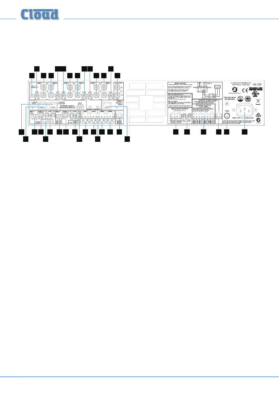
Rear panel description
4 6
8
22
9
6
7
5
20
21
11
1
2
3
3 3
3 3
3
1
1
1
1
1
12
7
10 10 10 10
16
13
17 19
18
14
15
1.
LINE 1 to LINE 6
– 6 pairs of RCA (phono) sockets for connection of music sources. Inputs are stereo, summed
internally to mono. See page 14.
2.
LINE 1/MEDIA – selects whether Music Source 1 is fed from LINE 1 inputs or the internal digital media player. This
push-button switch is only fitted to models 46-120
MEDIA
and 46-120T
MEDIA
.
3.
GAIN – preset trim control for each line input, providing ±10 dB of gain adjustment for input level matching. See page
4.
MIC 1/TEL – balanced microphone input on 3-pin 3.5 mm-pitch screw-terminal connector. See page page 15.
This input should be used in conjunction with the
ACCESS CONTACTS connector [7] for paging; it can also be
configured internally for use with a telephone system, See page 22.
5.
MIC 2 – balanced input for a second microphone; 3-pin 3.5 mm-pitch screw-terminal connector.
6.
GAIN – preset mic gain controls for MIC 1 and MIC 2, gain range 10 to 60 dB. See page 22.
7.
HF and LF – preset mic EQ controls. See page 22.
8.
ACCESS CONTACTS – 6-pin 3.5 mm-pitch screw-terminal connector for per-zone paging access by contact
closure. See page 16.
9.
MUSIC CONTROL – 12-pin 5 mm-pitch screw terminal connector for connection of RL-1/RSL-6 remote control
plates. See page 17.
10.
MUSIC CONTROL LEV & SRC – two push-button switches per zone which determine whether front panel music
source (
SRC) and level (LEV) controls will remain active when remote control plates are connected. See page 17.
11.
ZONE 1 FACILITY PORT – 8-pin RJ45 socket, for connection of LM-2 remote active modules, or as an auxiliary
input. See page 15.
12.
AUX OUT – unbalanced line level outputs for Zone 1 and Zone 2 at 0 dBu. See page 20.
13.
SPEAKER OUTPUTS – outputs for each zone on 8-pin 5 mm-pitch screw-terminal connector. See page 19.
These will be low impedance (min. load 4 ohms) on the 46-120 and 46-120
MEDIA
models, and 70 V-line on the 46-120T
and 46-120T
MEDIA
models (as standard). If one or more CXL-46T transformers have been retrofitted to a 46-120 or
46-120
MEDIA
, they may be either 100 V or 70 V-line. A checkbox area is provided below the connector for the installer
to indicate the configuration of each zone output.
14.
MOH/UTILITY OUTPUT – an auxiliary output whose source can be set by internal jumpers. The output is available
as both unbalanced line level (0 dBu) and a galvanically-isolated output suitable for driving 600 ohm inputs, as found on
telephone system MOH (Music On Hold) inputs. See page 19.
15.
MOH/UTILITY MIC 1 & MUSIC LEVEL – two pre-set controls, adjusting the level of the Mic 1 input and chosen
music source respectively at the Utility Output. See page 23.