Cdi-46 digital interface – Cloud Electronics 46-120TMedia User Manual
Page 18
46-120 Installation and User Guide V1.2
18
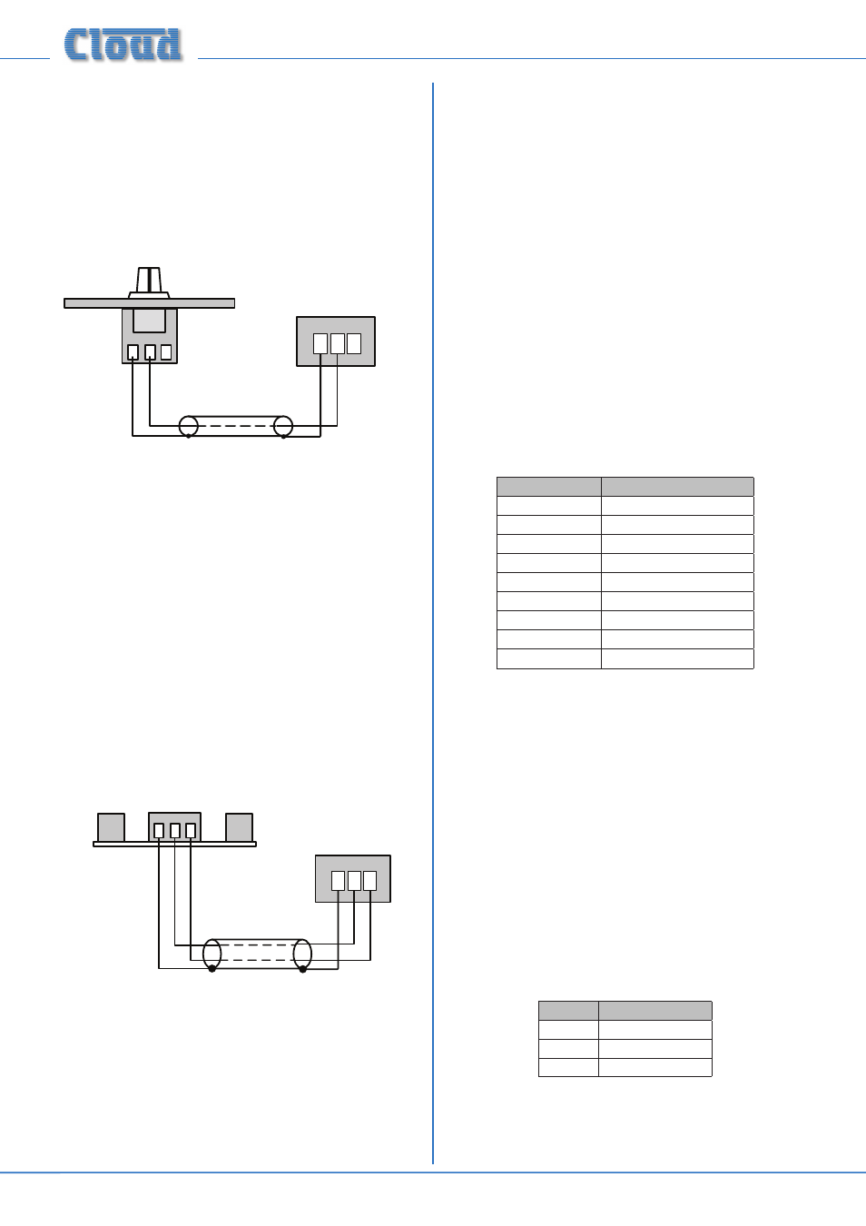
Connecting an RL-1 Series remote control plate
Wire the remote control plate as shown on the following
page. Either single-core screened or twin-and-screen cable
may be used; in the case of the latter, ignore one of the cores.
Maximum reliable cable run is 100 m.
1
2 3
REMOTE
SOURCE + LEVEL
1 2 3
REMOTE LEVEL CONTROL WIRING
RL-1
SINGLE-CORE SCREENED CABLE MAY BE USED
Before the RL-1 will operate, the zone’s
MUSIC CONTROL
port must be enabled by setting the
LEV push-button switch
([10] on page 12) to REMOTE (i.e., pressing it in). In this
setting, the zone’s front panel
MUSIC LEVEL control
becomes inoperative, but the
MUSIC SOURCE control is
still operative.
Connecting an RSL-6 Series remote control
plate
Wire the remote control plate as shown below. Twin-and-
screen cable should be used. Maximum reliable cable run is
100 m.
1 2 3
REMOTE SOURCE & LEVEL CONTROL WIRING
RSL-6
USE TWO-CORE SCREENED CABLE
1 2 3
REMOTE
SOURCE + LEVEL
Before the RSL-6 will operate, the zone’s
MUSIC CONTROL
port must be enabled by setting the adjacent push-button
switch ([12] on page 12) to REMOTE (i.e., pressing it in). In
this setting, both the zone’s front panel
MUSIC LEVEL and
MUSIC SOURCE controls become inoperative.
CDI-46 digital interface
The optional CDI-46 Digital Interface card may be retrofitted
to the 46-120 at any time. Full fitting instructions are supplied
with the card itself.
The CDI-46 equips the 46-120 with the Cloud CDPM/PM
Digital Paging Interface, and also allows the Mixer Amplifier’s
functions to be controlled from external systems using either
RS-232 serial data or TCP/IP commands via Ethernet.
The card includes a web browser interface via the Ethernet
port, allowing it to be configured using a simple Graphical
User Interface (GUI).
CDPM/PM interface
The Cloud CDPM/PM Digital Paging Interface (see [20] at
page 12) is an RJ45 socket allowing Cloud PM Series Paging
Microphones to be connected to the 46-120 using standard
screened Cat 5 cable. (Note that only screened Cat 5 should
be used.)
Use the standard Cat 5/RJ45 wiring convention as shown
below:
RJ45 PIN
CAT5
1
Brown + White
2
White + Brown
3
Green + White
4
White + Blue
5
Blue + White
6
White + Green
7
Orange + White
8
White + Orange
RJ45 Shell
Screen
Note that although multiple PM Series microphones may be
“daisy-chained” using the Digital Paging Interface, the 46-120
is only able to provide power for the “first” microphone in
the chain (i.e., the one connected directly to the 46-120). Any
other microphones in the system must be powered by one or
more external PSUs; see the PM Series Installation Guide for
full details, and also page 32.
NOTE: The front panel MIC 1 level controls will affect the
paging level from a PM Series paging microphone connected
via the CDPM/PM port.
RS-232 connection
The CDI-46 card is fitted with a bi-directional RS-232 port
(see [22] at page 12) on a 3-pin 3.5 mm-pitch screw
terminal connector. This should be wired as follows:
PIN
FUNCTION
1
Gnd
2
Data Rx
3
Data Tx
The port operates at default rate of 9600 baud; the data
format is 8 bits, no parity, 1 stop bit. This can be changed using
the card’s web interface.