Connector wiring, Rs-485 communication connections – Basler Electric RDP-110 User Manual
Page 20
12
9318100990 Rev H
Note
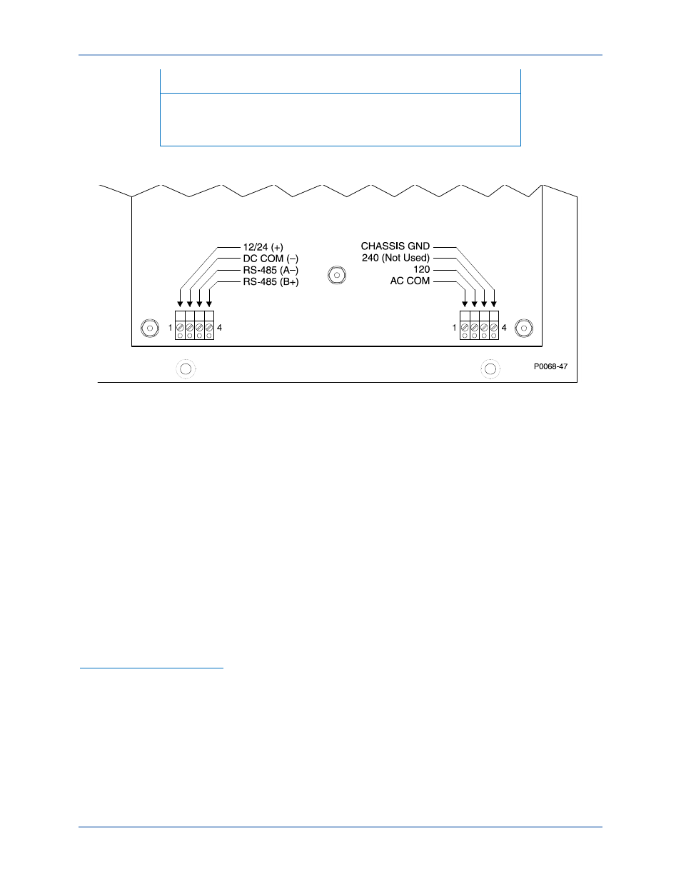
The 240 terminal is not functional and cannot be used. For ac control
power connections, only the 120 and AC COM terminals should be
used for application of 100/120 Vac nominal voltage.
Figure 6. RDP-110 Circuit Board Connections
Connector Wiring
Note the following guidelines when wiring the two circuit board connections:
•
The ground terminal connection should be made with wire no smaller than 16 AWG (1.5 mm
2
)
•
Other than the ground terminal, connections should be made with wire no smaller than 20 AWG
(0.5 mm
2
)
•
Maximum conductor size for each terminal is 12 AWG (4 mm
2
)
•
Strip the insulation from each wire to reveal 0.28 inches (7 millimeters) of exposed conductor
•
Apply no more than 4.4 in-lb (0.5 N
●m) of torque to each terminal screw
RS-485 Communication Connections
Twisted-pair conductors are recommended for the communication wiring between the DGC and
RDP-110.
Overly long wiring runs may impair communication between the DGC and RDP-110 unreliable. Do not
exceed an RS-485 conductor length of 4,000 feet (1,219 meters).
RS-485 Terminating Resistor
The RS-485 communication connection is internally terminated with a 100
Ω resistor. Connecting multiple
display panels may necessitate removal of this terminating resistor (R65). R65 is located in the lower, left
quadrant of the circuit board. The location of R65 is illustrated in Figure 7.
Consult standard TIA/EIA-485 for guidance on the electrical requirements of multipoint communication
systems.
4BInstallation
RDP-110