Basler Electric RDP-110 User Manual
Page 14
6
9318100990 Rev H
Locator
Description
F
The red Alarm LEDs light when the corresponding alarm setting is exceeded. Conditions
annunciated by the alarm LEDs include low coolant level, high coolant temperature, low oil
pressure, overcrank, overspeed, emergency stop activated, fuel leak/sender failure, and
sender failure. When the RDP-110 is used with a DGC-2020, DGC-2020ES, or
DGC-2020HD, the bottom two LEDs (Fuel Leak/Sender Failure and Sender Failure) can be
reprogrammed to indicate other alarm conditions. See Programmable Alarm and Pre-Alarm
Configuration for information about configuring the two programmable alarm indicators.
G
Red Switch Not In Auto LED lights when the DGC is not operating in Auto mode.
Programmable Alarm and Pre-Alarm Indicator Configuration
When used with a DGC-2020, DGC-2020ES, or DGC-2020HD, the RDP-110 has the added capability of
programmable alarm and pre-alarm indicators. This ability applies only to the DGC-2020, DGC-2020ES,
or DGC-2020HD and is not available when the RDP-110 is paired with the DGC-500 or DGC-1000.
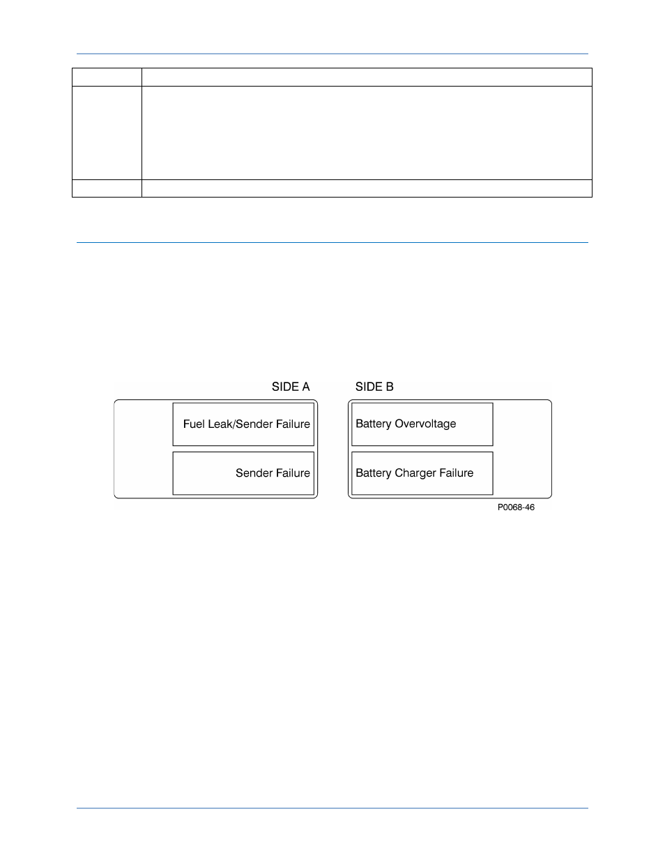
Up to two alarm LEDs and two pre-alarm LEDs may be reprogrammed to suit the needs of a particular
application. The two bottommost alarm LEDs are pre-configured in DGC logic to annunciate a fuel
leak/sender failure and sender failure. The two bottommost pre-alarm LEDs are pre-configured in DGC
logic to annunciate battery overvoltage and a battery charger failure. These LEDs are labeled as such
with replaceable cards (Figure 3) that can be relabeled to match the function of each programmable
indicator.
Figure 3. Programmable Alarm and Pre-Alarm Label Cards
Information about configuring DGC logic to provide other alarm and pre-alarm annunciations is available
in the appropriate DGC instruction manual. To re-label the RDP-110 programmable alarm and pre-alarm
LEDs, perform the following steps.
1.
Print the label text on readily-available address label sheets. The label cards accommodate
adhesive-backed labels measuring 0.5 by 1.75 inches. Avery part number 18167 is suitable for
this purpose.
2.
Remove all control power from the RDP-110.
3.
Remove the four Phillips screws from the front panel and separate the front panel from the
conduit box. Disconnect the two connectors attached to the circuit board mounted to the front
panel. When handling the front panel, avoid touching the circuit board.
4.
Lay the front panel face-down on a suitable work surface.
5.
Grasp the tab of the label card to be changed and pull free. The two label cards are located near
the two lower corners of the circuit board. When facing the back of the panel, the pre-alarm label
card is on the left and the alarm label card is on the right.
6.
Apply the labels created in step 1 to the label cards. The rectangle outlines on each label card
serve as guides for attaching the labels.
1BControls and Indicators
RDP-110