Introduction, Rs contact output state, Table a-1. rs contact operation table – Basler Electric BE1-79A User Manual
Page 61: Appendix a • rs contact application
9310200990 Rev J
BE1-79A RS Contact Application
A-1
APPENDIX A • RS CONTACT APPLICATION
Introduction
The functionality of the RS contact in the BE1-79A relay emulates that of an ACR reclosing relay. The RS
contact can be applied to disable the instantaneous trip circuit of protection relays after any close attempt,
typically leaving only time overcurrent protection in service. It can also be used to block transformer load
tap changer (LTC) changes during a reclosing sequence. For transmission line applications, it has been
used to permit operation of other automatic devices such as motor operated switches in line sectionalizing
operations.
RS Contact Output State
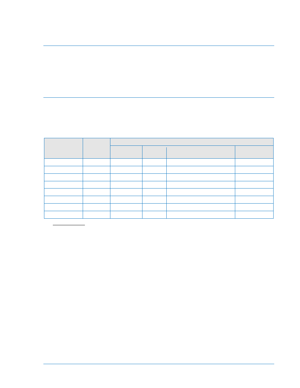
To illustrate RS contact operation, Table A-1 lists the possible setting combinations for RS Contact switch
S5 (NO or NC) and the SP-79ARS command mode (D or E). Switch S5 can be selected as normally open
or normally closed to simulate the jumper-selectable RS contact in an ACR relay. Independent of the SP-
79ARS command mode, the S5 NO/NC selection assigns the state of the RS contact when the relay
power supply is de-energized.
Table A-1. RS Contact Operation Table
SP-79ARS
Command
Parameters
S5
Position
RS Contact State When:
BE1-79A
Power Off
BE1-79A
Reset
Applied
Removed
D,0,145
NC
Closed
Closed
Opens as soon as 52b makes
Closes at 145 s
D,2.5,145
NC
Closed
Closed
Opens at 2.5 s
Closes at 145 s
D,0,145
NO
Open
Open
Closes as soon as 52b makes
Opens at 145 s
D,2.5,145
NO
Open
Open
Closes at 2.5 s
Opens at 145 s
E,0,145
NC
Closed
Open
Closes as soon as 52b makes
Opens at 145 s
E,2.5,145
NC
Closed
Open
Closes at 2.5 s
Opens at 145 s
E,0,145
NO
Open
Closed
Opens as soon as 52b makes
Closes at 145 s
E,2.5,145
NO
Open
Closed
Opens at 2.5 s
Closes at 145 s
SP-79ARS command syntax is SP-79ARS[=
the RS element is de-energized or “dropped out” when power is applied to BE1-79A terminals 5 and 6.
Mode E indicates that the RS element is energized or picked up when power is applied to BE1-79A
terminals 5 and 6.
Table A-1 Notes
In Applied mode, the RS contact functions opposite of the way it does in Removed mode and BE1-79A
Power Off mode.
When the ac or dc operating power applied to terminals 5 and 6 is interrupted during a reclose sequence,
the RS contact returns to the BE1-79A Power Off state until operating power is restored and the reclosing
sequence is resumed.
The mode of the RS contact offers the ability to invert the relay logic. In D (de-energized) mode, the
position of the RS contact will follow the classic definition of relay logic:
•
If RS logic is 0, the RS relay coil is de-energized.
•
If RS logic is 1, the RS relay coil is energized.
In E (energized) mode, the relay logic is inverted and the RS coil is normally energized and then de-
energized when the RS logic goes to 1. The effect is:
•
If RS logic is 0, the RS relay coil is energized.
•
If RS logic is 1, the RS relay coil is de-energized.
Note that if E logic is selected and the relay RS logic is 0, the RS coil will be energized and holding the
output contact against its internal spring. However, if the relay loses power at this point, the RS contact
will change state to the open/closed position dictated by RS Contact switch S5. Table A-1 is based on
these explanations and will be referred to throughout the remainder of this appendix.