Motor voltage, Contact sensing inputs, Motor voltage -7 – Basler Electric BE1-79A User Manual
Page 47: Contact sensing inputs -7, Figure 5-6. contact sensing jumpers, Figure 5-7. contact sensing jumper locations
9310200990 Rev J
BE1-79A Installation and Configuration
5-7
Motor Voltage
No adjustment is required for the motor voltage applied at terminals 5 and 6. The applied voltage can
range from 120 to 240 Vac or 125 to 250 Vdc. These terminals serve as the input to the BE1-79A power
supply and control functions.
Contact Sensing Inputs
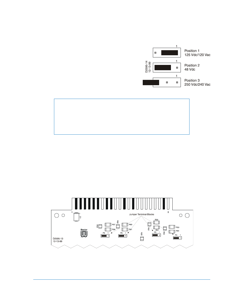
Energizing levels for contact sensing inputs V1 through
V4 are jumper selectable for operation at three nominal
voltage levels. Jumper P3 controls the operating voltage
for V1, P4 controls V2, P5 controls V3, and P6 controls
V4. Nominal voltage levels of 125 Vdc/120 Vac, 48 Vdc,
or 250 Vdc/240 Vac may be selected. Figure 5-6
illustrates the three possible jumper positions for P3
through P6. Input V5 is dedicated to monitoring the relay
power supply input and is not jumper selectable.
Figure 5-6. Contact Sensing Jumpers
NOTE
In certain applications where 240 Vac control voltage is used, control circuit
feedback can occur through system inductive coupling. This feedback can
result in erroneous signals, causing relay operation. If there is a potential for
control circuit feedback, the jumper selectable voltage range should be
changed from the 48 Vdc factory default setting to a higher position. Selections
are provided in Table 3-1.
The following paragraphs describe how to locate and change the position of the contact-sensing jumpers.
1. Remove the four Phillips screws from the front panel and separate the front panel from the relay
chassis.
2. Carefully grasp and remove the Digital circuit board (top circuit board) from the relay chassis. Take
care not to damage any of the circuit board components. Observe all electrostatic discharge (ESD)
precautions when handling the circuit board. Place the circuit board on an ESD-safe surface.
3. Locate the four jumper terminal blocks (P3 through P6) on the circuit board. The jumper terminal
blocks are located on the component side of the circuit board near the rear contact fingers (see
Figure 5-7). Each terminal block has three pins and each jumper is factory installed on pins 2 and 3.
Figure 5-6 illustrates each of the three jumper positions.
Figure 5-7. Contact Sensing Jumper Locations
4. To select operation at 125 Vdc or 120 Vac, remove the jumper from pins 2 and 3 and position it on
pins 1 and 2. To select operation at 250 Vdc or 240 Vac, remove the jumper from pins 2 and 3 and
position it on pin 3 for storage. (Only pin 3 of the terminal block should be covered.)