Delayed reclose testing, Acr11a style, Acr11b style – Basler Electric BE1-79A User Manual
Page 54: Acr11a and acr11b styles, Delayed reclose testing -2, Acr11a style -2, Acr11b style -2, Acr11a and acr11b styles -2, Table 6-2. delayed reclose testing commands
6-2
BE1-79A Testing
9310200990 Rev J
f. After 20 seconds, L2 will light for three seconds
g. After 30 seconds, L2 will light for three seconds
h. After 40 seconds, the front panel Lockout led and Lockout indicator L3 will light
4. Place Test switch S1 in the 52a position and observe that after five seconds, the front panel Reset
LED and Reset indicator L1 light.
5. Place Test switch S1 in the 52b position. When Reclose indicator L2 lights, momentarily place Test
switch S1 in the 52a position and verify that L2 turns off.
6. Place Test switch S1 in the 52b position and verify that after 10 seconds, L2 lights for three seconds.
7. Place Test switch S1 in the 52a position and verify that after 15 seconds, the front panel Reset LED
and Reset Indicator L1 light.
Delayed Reclose Testing
ACR11A Style
Place Style Configuration switches S1, S2, and S3 in the A position. Place Instantaneous Reclose
Jumper switch S4 in the EXT position. Place RS Contact switch S5 in the NO position.
ACR11B Style
Place Style Configuration switches S1, S2, and S3 in the B position. Place Instantaneous Reclose
Jumper switch S4 in the EXT position. Place RS Contact switch S5 in the NO position.
ACR11A and ACR11B Styles
1. Place Test switch S1 in the 52a position and apply 120 Vac to the relay and test circuit.
2. Connect a PC with a serial port and suitable communication software to the relay serial port. Transmit
the settings of Table 6-2 to the relay. (These settings correspond to the illustration of Figure 3-5.)
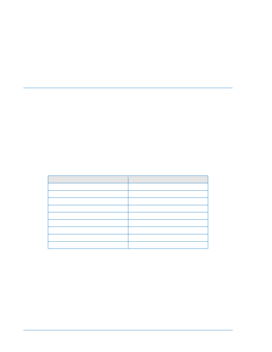
Table 6-2. Delayed Reclose Testing Commands
Command
Time Between Recloses
ACCESS=
N/A
SP-79A1=10.0,20.0
10 – 0 = 10 s
SP-79A2=30.0,40.0
30 – 10 = 20 s
SP-79A3=50.0,60.0
50 – 30 = 20 s
SP-79A4=70.0,80.0
70 – 50 = 20 s
SP-79ALO=180,185
180 – 70 = 110 s
SP-79ARS=D,10,9
N/A
EXIT
N/A
Y
N/A
3. Place Test switch S1 in the 52b position and observe that the following sequence of events occur.
a. Front panel Reset LED turns off
b. Reset indicator L1 turns off
c. Front panel In Sequence LED lights
d. After 10 seconds, Reclose indicator L2 will light for three seconds
e. After 30 seconds, L2 will light for three seconds
f. After 50 seconds, L2 will light for three seconds
g. After 70 seconds, L2 will light for three seconds
h. After 180 seconds, the front panel Lockout led and Lockout indicator L3 will light
4. Place Test switch S1 in the 52a position and observe that after five seconds, the front panel Reset
LED and Reset indicator L1 light.
5. Place Test switch S1 in the 52b position. When Reclose indicator L2 lights 10 seconds later, place S1
in the 52a position momentarily and verify that Reclose indicator L2 turns off.