Reset switch, Relay installation, Communication connections and settings – Basler Electric BE1-79A User Manual
Page 49: Communication connector, Reset switch -9, Relay installation -9, Communication connections and settings -9, Communication connector -9, Table 5-1. rs-232 pin functions
9310200990 Rev J
BE1-79A Installation and Configuration
5-9
If the microprocessor closes the alarm output due to a failure, all three front panel LED indicators will be
lit. The failure indication can be cleared by cycling operating power to the relay.
Refer to Section 4, Communication Commands, Command Descriptions for a detailed description of the
SP-ALM command.
Reset Switch
The front panel reset switch performs the same function as the manual clutch release in ACR reclosers.
Power must be applied to terminals 5 and 6 for this function to perform a reset.
Relay Installation
Perform the following procedure to install the BE1-79A relay.
1. Adjust Style Configuration Switches S1, S2, and S3 and Instantaneous Reclose Jumper Switch S4 to
the correct positions for your application.
2. Insert the BE1-79A relay and close the cradle latches to lock the relay into the case.
3. Install the connection plugs.
4. Enter the desired settings through the front serial communication port. Information about configuring
HyperTerminal and Terminal for communication with the BE1-79A is provided in Appendix B,
Terminal Communication. Refer to Section 4, Communication Commands for information about relay
communication and ASCII commands.
5. Install the relay cover.
Communication Connections and Settings
The required connections and settings for BE1-79A communication are described in the following
paragraphs.
Communication Connector
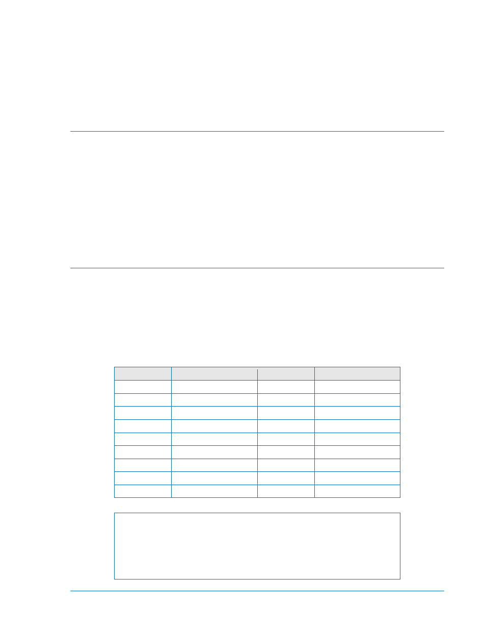
The BE1-79A uses a standard RS-232 (DB-9) female connector located on the front panel. Connector pin
numbers, functions, names, and signal directions are listed in Table 5-1. Figure 5-8 provides a connection
diagram for connecting the BE1-79A relay to a personal computer (PC).
Table 5-1. RS-232 Pin Functions
Pin
Function
Name
Direction
1
Shield
—
N/A
2
Transmit Data
TXD
From Relay
3
Receive Data
RXD
Into Relay
4
N/C
—
N/A
5
Signal Ground
GND
N/A
6
N/C
—
N/A
7
N/C
—
N/A
8
N/C
—
N/A
9
N/C
—
N/A
NOTE
The RS-232 communication ports are not equipped with request-to-send
(RTS) and clear-to-send (CTS) control lines. This makes the BE1-79A
incompatible with systems that require hardware handshaking or systems that
use self-powered RS-232 to RS-485 converters connected to the RS-232
ports.