Minimum voltage detection, Contact sensing options, Power supply – Basler Electric BE1-25 User Manual
Page 36: Power supply status output option, Minimum voltage detection -2, Contact sensing options -2, Power supply -2, Power supply status output option -2, Figure 3-1. functional block diagram -2
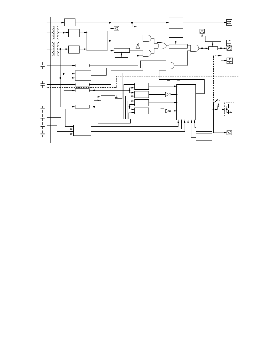
Figure 3-1. Functional Block Diagram
Minimum Voltage Detection
Minimum voltage detection circuitry enables the TIME DELAY timer when both line and bus are within
operating range of the relay. Voltage sensing circuits are guaranteed to operate at a minimum voltage of
60 volts. They are guaranteed not to operate at voltages less than 20 volts. Some units may operate at
voltages in between these two levels because of the individual characteristics of specific components.
Minimum voltage detection is usually in the range of 45 to 55 volts.
Contact Sensing Options
Before any relay output can occur, there must be an initiating signal from external contacts. Contact
sensing circuitry allows the relay to monitor circuit breaker status (52b) and various conditions selected by
the user. (Contact requirements are provided in the Specifications.)
In any sync-check relay, all of the contact sensing inputs supplied must use one of two methods.
1. Isolated sensing (Option 1-5), uses current supplied by the relay to monitor the isolated contacts.
2. Non-isolated sensing (Option 1-4), monitors an external dc source whose nominal voltage is
equal to the input to the BE1-25 power supply.
Power Supply
Operating power for the relay circuitry is supplied by a wide range, electrically isolated, low-burden power
supply. Power supply operating power is not polarity sensitive. The front panel power LED and power
supply status output indicate when the power supply is operating. Power supply specifications are listed in
Table 1-1.
Power Supply Status Output Option
The power supply status output relay (Option 3-6) has normally closed (NC) output contacts. The relay is
energized upon power-up, thus opening its contacts. The contacts will remain open as long as normal
relay operating voltage is maintained. However, if the power supply voltage falls below the requirements
for proper operation, the power supply status output relay de-energizes, thus closing the NC output
contacts.
01-30-01
D1058-04.vsd
OPERATING
POWER
BUS
LINE
EXPAND
PHASE
ANGLE
OPTION
OPTIONAL
EXTERNAL
CONTACTS
LB
DB OR BOV
LL
DL OR LOV
52b
POWER
SUPPLY
CROSS
ZERO
ZERO
CROSS
PHASE
DIFFERENCE
MEASUREMENT
POWER
-2 OR -3
JUMPER
ON PCB
TO INTERNAL
CIRCUITRY
AND
AND
OR
POWER
SUPPLY
SENSOR
PHASE
ANGLE
SELECTOR
COMPARATOR
AND
AND
TIMER
TIME DELAY
SWITCHES
PHASE
SYNC.
OUTPUT
SYNC.
OUTPUT
AUX.
OUTPUT
P.S. STATUS
ISOLATION
MINIMUM
VOLTAGE
DETECTION
ISOLATION
FILTER
ISOLATION
FILTER
FRONT PANEL SETTINGS
PEAK OR AVG
DETECTOR
V
LL LB IF MODE 1:
(LL OV)(LB OV) IF MODE 2
LB
DB OR BOV
LL
DL OR LOV
VOLTAGE
MONITOR
SELECTION
LOGIC
MODE
SWITCHES
CONDITION
SWITCHES
MONITOR
ACCEPT
PATHS
ALTERNATE
MONITOR
VOLTAGE
OUTPUT
OPTION
DEPENDING
VOLT.
SYNC-CHECK CIRCUITRY
VOLTAGE MONITOR OPTIONS
.
.
.
ON OUTPUT
PEAK OR AVG
DETECTOR
PEAK OR AVG
DETECTOR
PEAK OR AVG
DETECTOR
PEAK OR AVG
DETECTOR
3-2
BE1-25 Functional Description
9170200990 Rev U