Figure 1-6. style number identification chart -8, Figure 1-6. style number identification chart, Be1-25 – Basler Electric BE1-25 User Manual
Page 18
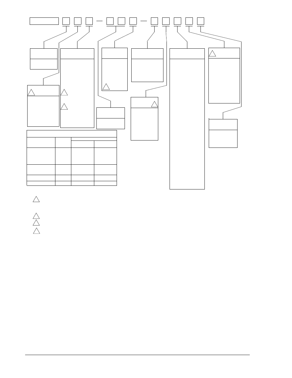
Figure 1-6. Style Number Identification Chart
OPTION 3
OPTION 4
OPTION 2
OPTION 1
SUPPLY
RANGE
SENSING INPUT
M
POWER
BE1-25
MODEL NO.
SENSING INPUT
TYPE
M) Single Phase
Voltage
OUTPUT
TIMING
TARGET
N) None
A) One Internally
Operated
B) One Current
Operated
F) Semi-Flush
Mounting
P) Projection
Mounting
1) 120 Vac, 1-99°
Phase Angle
Setting
9) 120 Vac, 1-99°
Phase Angle
Setting With
Expandable
Window
1
E) Sync-Check
NO Relay
F) Sync-Check
NO Relay with
Push-to-
Energize
Output
G) Sync-Check
NO Relay and
Voltage Monitor
SPDT Relay
H) Sync-Check
NO Relay and
Voltage Monitor
SPDT Relay
with Push-to-
Energize
Output (for
both relays)
4
4
A6) 0.1-99 Sec.
A7) 1-99 Cycles
O) 48 Vdc
P) 125 Vdc or
100/120
Vac
R) 24 Vdc
T) 250 Vdc or
240 Vac
3
4) Non-Isolated
Contact
Sensing
Input
5) Isolated
Contact
Sensing
Input
N) None
R) Line and Bus
Voltage Monitor
and Voltage
Difference with
PC Bd Mounted
Switches
S) Line and Bus
Voltage Monitor
with PC Bd
Mounted Switches
T) Voltage Difference
Voltage Monitor
and Voltage
Difference with
External Contact
Inputs
V) Line and Bus
Voltage Monitor
with External
Contact Inputs
0) None
1) Sync-Check
Auxiliary Output
NO Relay
2) Sync-Check
Auxiliary Output
NC Relay
3) Sync-Check
Auxiliary Output
SPDT Relay
6) Power Supply
Status Output
1
CONTACT SENSING MODULES
(Required when Type T Power Supply is specified)
Module Ordering Number
9 1702 06 106
Non-Isolated
Contact Sensing
Isolated
Contact Sensing
Number of
Contacts
Sensed
Relay Options
Voltage Monitor
with External
Contact Inputs
plus Expandable
Phase Window
Voltage Monitor
with External
Contact Inputs
Expandable Phase
Window
None of the above
9 1702 06 100
9 1702 06 101
9 1702 06 107
9 1702 06 104
9 1702 06 110
9 1702 06 105
9 1702 06 111
6
5
2
1
NOTES:
When Sensing Input Range 9 is Selected from the
Style Chart, Option 3 must be 0.
All relays are supplied in an S1 size case.
Requires Contact Sensing Module. See Table in this chart.
Not available if Option 2 is B, N, or T.
1
3
4
2.
D434-006.vsd
01-30-01
A) Average
Voltage Monitor
and Voltage
Difference with
PC Bd Mounted
Switches
U) Line and Bus
C) Average
B) Average Voltage
Difference
Voltage Monitor
and Voltage
Difference with
External Contact
Inputs
For more information on contact sensing see Specifications.
5
5
1-8
BE1-25 General Information
9170200990 Rev U