Basler Electric BE1-25 User Manual
Page 15
∆
V V sin
B
=
θ
(2)
θ
∆
=
−
sin
V
V
1
B
(3)
where:
∆
V = Voltage Difference
V
L
= Line Voltage
V
B
= Bus Voltage
θ
= Phase Angle
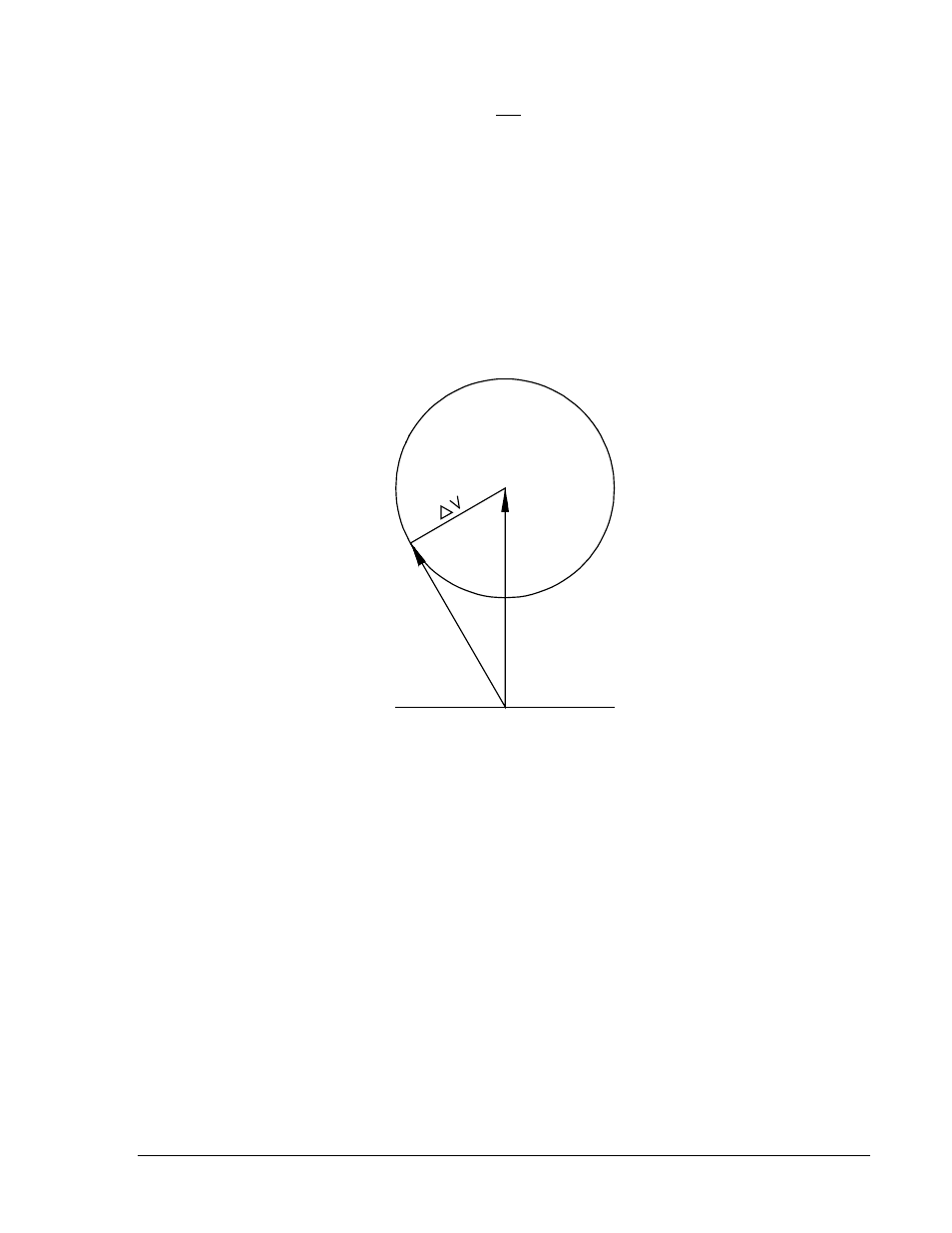
Note that the point where
V
L
is tangent to the voltage difference circle represents the most extreme
condition of
θ
for a closure. Assuming that a constant voltage difference exists, the following condition is
valid: If the magnitude of the line voltage decreases, the phase angle must also decrease to allow sync-
acceptance. Therefore, the minimum line voltage possible for sync-acceptance occurs at zero phase
angle.
Figure 1-4. Closing Zone Calculation Diagram (Phasor Sensing)
Option 2-A, 2-B, or 2-C (Average Voltage Difference)
This option is similar to option 2-T, 2-R, or 2-U except for the sensing method. This option provides
average voltage sensing instead of phasor voltage sensing. This provides a constant ∆V setting
independent of the phase relationship between the line and bus voltages.
Figure 1-5 may be used as an aid in formulating the voltage difference control settings. Note that the
center reference phasor (
V
B
) represents the monitored bus voltage, while the adjacent phasor (
V
L
)
represents the monitored line voltage. The voltage difference control (∆V) forms an area of acceptance
limit.
VL
VB
P0004-37
θ
9170200990 Rev U
BE1-25 General Information
1-5