Thermostat, Ptional, Quipment – Avalon Firestyles DVS Insert-1996 to 2000 User Manual
Page 34: Ontinued
P
AGE
34
O
PTIONAL
E
QUIPMENT
(C
ONTINUED
)
Thermostat
(Part # 99300650)
!
Do not connect 120 VAC to the gas control valve or wiring of this unit.
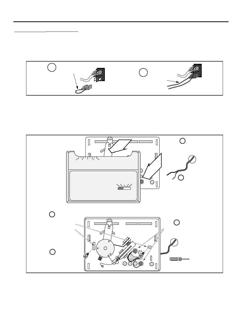
1
Expose the back of the on/off switch (it is either on the upper right corner of the surround panels or
on the controls bracket to the right of the gas control valve). Remove the green jumper wire and
attach the thermostat wire to the back of the on/off switch (see the illustration below).
a
Remove the green
jumper wire.
Attach the quick connects
from the wire to the two
posts on the on/off switch.
b
2
Run the thermostat wire behind the surround panels. Pull through all the slack (you may wish to
wrap the wire in electrical tape to prevent damage to the wire). Determine a location for the
thermostat that is within range of the 50' length of thermostat wire. It should be centralized in the
room and away from the heater. The wire may be routed externally on the wall or behind the wall
(preferred).
3
Install the thermostat following the directions below.
50 60 70 80 90
50 60 70 80 90
Robertshaw
Run the thermostat wires
through the wall (cut off excess
wire, leaving 6Ó of slack).
Pull the cover off the thermostat
Expose 1/2Ó of wire and
attach to these two posts.
Standard
Screwdriver
Attach the thermostat to
the wall through these
two holes.
a
b
c
d
Re-attach the cover
removed in step ÒaÓ.
e