Ip module, Commlink 5 baud rate setting, 9technical guide – Auto-Zone Control Systems IP Module Kit Installation Guide for the IP Module Kit Used with CommLink IV & 5 (Version 01N) User Manual
Page 9: Setting the commlink 5 baud rate, High low baud
IP MODULE
9
Technical Guide
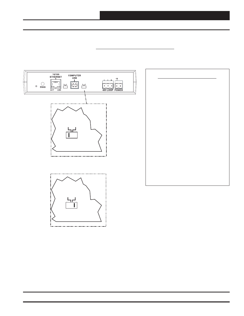
CommLink 5 Baud Rate Setting
Setting the CommLink 5 Baud Rate
CommLink 5 Baud Rate Setting
The Baud Rate Switch Located On The Back Of
The CommLink 5 Housing Must Be Set Correctly
For Your Specific Application In Order For The
CommLink 5 To Function At Maximum Efficiency.
The
Should Be Set To “High” In The
Following Situations:
You Are Using Only
2 Controllers, Only
GPC-XP Controllers, or Only VCB-X
Controllers On Your System.
The CommLink 5 Is Factory Set For Low Baud
Rate Applications.
Baud Rate
The Baud Rate Should Be Set To “Low” In The
Following Situations:
You Are Using Orion Controllers Or Are
Using Orion Controllers In Combination
With VCB-X or GPC-XP Controllers. For
Example, VCB-X or GPC-XP Controllers
With VCM-X or VCM Controllers.
AZ
MUL
T
IPLE
HIGH
SINGLE
LOW
BAUD
LOOP
R
(+)
24V
GND
SHLD
T(
-)
SERIAL #
Switch Set To High Baud
Rate (115,200)
Back of CommLink 5
HIGH
LOW
BAUD
Switch Set To Low Baud
Rate (Anything Less Than
115,200)
HIGH
LOW
BAUD
Figure 5: Setting the Baud Rate