Ip module, Commlink iv communications setting, 7technical guide – Auto-Zone Control Systems IP Module Kit Installation Guide for the IP Module Kit Used with CommLink IV & 5 (Version 01N) User Manual
Page 7: Setting the commlink iv communications setting
IP MODULE
7
Technical Guide
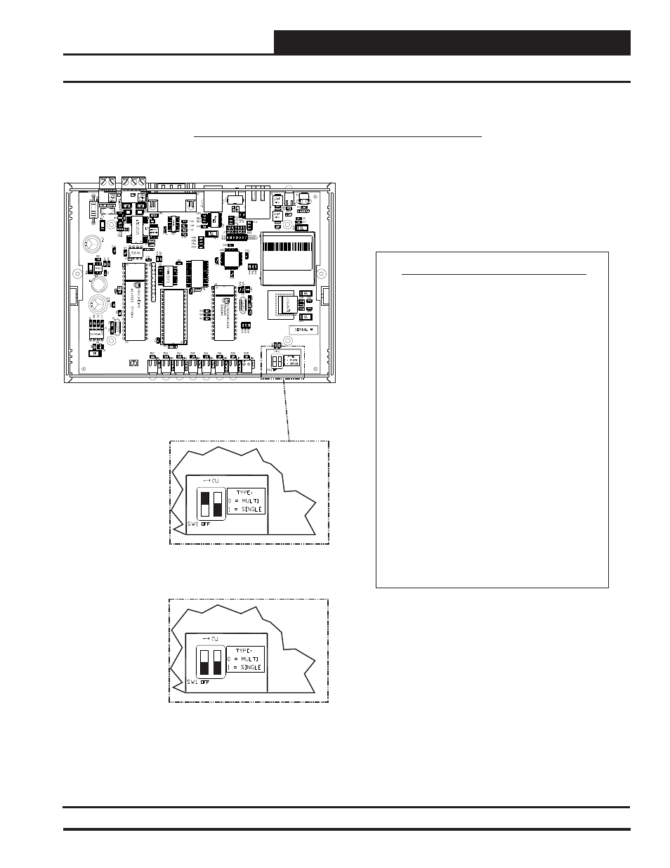
CommLink IV Communications Setting
ALTERA
EPM3032
WattMaster Controls Inc.
COMMLINK IV
YS102074
REV6
MADE IN USA
The SW1 DIP Switch Located On The Circuit Board
Inside The CommLink IV Housing Must Be Set
Correctly For Your Specific Application In Order To
Function Properly.
To Check And/Or Set The SW1 Dip Switch, First
Remove The (2) Enclosure Screws That Hold The
Top And Bottom Of The CommLink IV Enclosure
Together. Remove The Top Half Of The Enclosure To
Access The Circuit Board And Dip Switches.
The
DIP Switch Setting
Be Set To
“Multiple”
When There Is A MiniLink Wired To Your System.
The CommLink IV Is Factory Set
For Multiple Loop Applications.
SW1
Must
In The Following Situation:
The SW1 DIP Switch Setting Must Be Set To “Single”
In The Following Situation:
When There IS NO MiniLink Wired To Your
System.
Replace The CommLink IV Cover And Secure The
Enclosure Halves Back Together With The (2)
Enclosure Screws That Were Previously Removed.
LANTRONIX WiPort NR
00-20-4A-89-6B-EE
WP5001000-01 Rev.A11
Pat. 4972,470 06W21
Made in Taiwan
DIP Switch 1 & 2 Off =
Multiple Loop Communications
DIP Switch 1 On & 2 Off =
Single Loop Communications
Setting the CommLink IV Communications Setting
CommLink IV Communications Setting
Figure 3: CommLink IV Communication Settings