Ip module, Commlink iv with ip module connections and wiring, 10 technical guide – Auto-Zone Control Systems IP Module Kit Installation Guide for the IP Module Kit Used with CommLink IV & 5 (Version 01N) User Manual
Page 10: Commlink iv with ip module connection & wiring
IP MODULE
10
Technical Guide
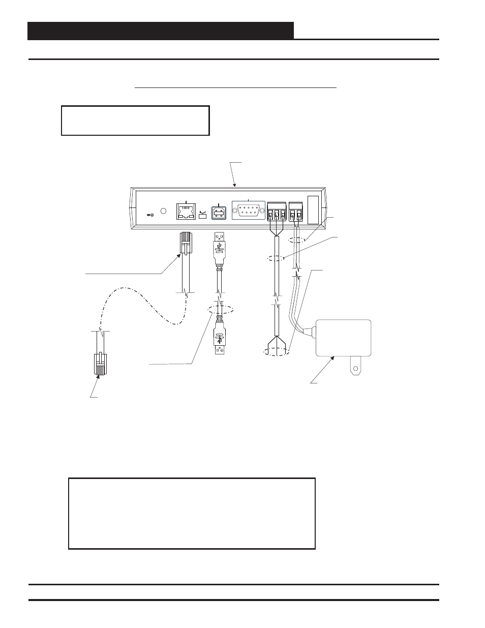
CommLink IV with IP Module Connections and Wiring
Figure 6: CommLink IV with IP Module Connection & Wiring
24 VAC Power
If Desired A 24 VAC Transformer
(Not Included) Rated At 12 VA
Minimum May Be Used Instead
Of The Supplied Power Pack.
Use 18 Gauge Minimum
2 Conductor Wire Between The
Transformer & CommLink IV
Terminals.
120 to 24 VAC Power Pack
(Included With CommLink IV)
Connect To 120/1/60 Duplex
Receptacle (By Others).
CommLink IV with IP Module
CommLink IV with IP Module Connection & Wiring
NOTES:
1.) Use 18 Gauge Minimum 2 Conductor Twisted Pair With Shield Cable Belden #82760
(Not Included) Or Equivalent To Connect The CommLink IV To A MiniLink Or MiniLink PD
On The Network Loop Or To Controllers On A Local Loop.
2.) The CommLink IV Cannot Communicate With The Control System Through Its
Ethernet Port And USB Port At The Same Time.
3.) All Wiring Must Conform To Applicable Federal, State & Local Electrical Wiring Codes.
18 Gauge 2 Conductor
With Shield (Not Included)
See Note 1.
Connect To A
MiniLink PD, MiniLink
Or Other Controller As
Required By Your
Specific System
Wiring Instructions.
See Note 1.
MODEM
RS-232
Serial #
COMPUTER
USB
10/100
ETHERNET
DIAG
24V
T G R
GND
485 LOOP POWER
Reset
Default
Values
ACT
LNK
USB
Config
Normal
When Connecting Directly To Your
Computer, Use The
10
Crossover
Prefabricated
Ft.
Long
CAT5 Ethernet Cable
(Included).
Connect Directly To Your Computer
(Crossover CAT 5) Or Connect To An
Available 10/100 BaseT Port On Your
LAN (Standard CAT 5).
WARNING! Do Not Have Your Ethernet Connection
And USB Connection Connected At The Same Time.
This Could Cause Unreliable Communications.
Supplied With CommLink
But Not Required For IP
Module Installation. See
Note 2.