2 leds, Table 3-8, Front panel leds – Artesyn MVME721x RTM Installation and Use (April 2015) User Manual
Page 48: Controls, leds, and connectors
Controls, LEDs, and Connectors
MVME721X RTM Installation and Use (6806800M42D)
48
3.3.2
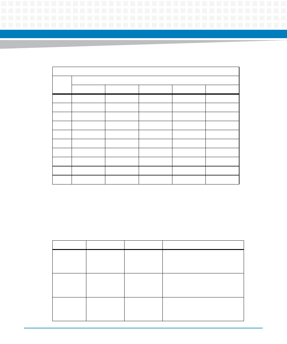
LEDs
There are two sets of ACT and SPEED LEDs, one set for each Ethernet connector. They are
described in the next table. For LED positions, please see
23
PMC IO 46
NC
PMC IO 45
E2_3 -
Serial 3 RTS
24
PMC IO 48
NC
PMC IO 47
E2_3+
GND
25
PMC IO 50
NC
PMC IO 49
GND
Serial 4 RX
26
PMC IO 52
NC
PMC IO 51
E2_2 -
GND
27
PMC IO 54
NC
PMC IO 53
E2_2 +
Serial 4 TX
28
PMC IO 56
NC
PMC IO 55
GND
GND
29
PMC IO 58
NC
PMC IO 57
E2_1 -
Serial 4 CTS
30
PMC IO 60
NC
PMC IO 59
E2_2 +
GND
31
PMC IO 62
GND
PMC IO 61
GND
Serial 4 RTS
32
PMC IO 64
+5V
PMC IO 63
+5V
GND
Table 3-7 VME Backplane P2 Connector Pin Assignments (continued)
P2 Connector
Pin
Name
Signal Description
Row A
Row B
Row C
Row D
Row Z
Table 3-8 Front Panel LEDs
Label
Location
Color
Description
GENET1
SPEED
Front panel
Integrated
RJ45 LED
Off
Amber
Green
No link
10/100BASE-T operation
1000 BASE-T operation
GENET1
ACT
Front panel
Integrated
RJ45 LED
Off
Blinking Green
No activity
Activity proportional to bandwidth
utilization
GENET2
SPEED
Front panel
Integrated RJ45
LED (Left)
Off
Amber
Green
No link
10/100BASE-T operation
1000BASE-T operation
- ARTM-9405 16x10GbE Installation and Use Guide (May 2014) (64 pages)
- ATCA 7370 / ATCA 7370-S Installation and Use (January 2015) (256 pages)
- ATCA 7370 / ATCA 7370-S Installation and Use (September 2014) (254 pages)
- ARTM-831X Installation and Use (June 2014) (346 pages)
- ATCA-7350 - Integrating with Workbench User Guide (September 2014) (34 pages)
- ATCA-7350 Installation and Use (September 2014) (208 pages)
- ATCA-7365-CE Installation and Use (May 2014) (306 pages)
- ATCA-7365-CE Installation and Use (Jan 2015) (300 pages)
- ATCA-7365-CE Installation and Use (May 2014) (294 pages)
- ATCA-7368 Installation and Use (June 2014) (222 pages)
- ATCA-7475 Installation and Use (October 2014) (284 pages)
- ATCA-7480 Installation and Use (April 2015) (330 pages)
- ATCA-8330 Installation and Use (April 2015) (236 pages)
- ATCA-8320 Installation and Use (May 2014) (456 pages)
- ATCA-9305 User's Manual (May 2014) (270 pages)
- ATCA-9405 Installation and Use (October 2014) (168 pages)
- ATCA-F120 Installation and Use (August 2014) (122 pages)
- ATCA-F140 Installation and Use (September 2014) (138 pages)
- ATCA-MF106 Installation and Use (September 2014) (86 pages)
- Centellis-4440/AXP1440 Installation and Use (September 2014) (208 pages)
- Centellis 4410 (AXP-1410) Installation and Use (July 2014) (202 pages)
- Centellis 2100 Release 3.0 Installation and Use (March 2015) (192 pages)
- Centellis 2100 Release 3.0 Installation and Use (March 2015) (176 pages)
- Centellis 2000 User Card-10GE Installation and Use (May 2014) (54 pages)
- Centellis 2000 User Card-10GE with Telco Alarm Installation and Use (May 2014) (60 pages)
- COMX-CAR-210 Installation and Use (August 2014) (76 pages)
- COMX-P1022 Installation and Use (July 2014) (84 pages)
- COMX-P2020 Installation and Use (February 2015) (100 pages)
- COMX-CORE Series Installation and Use (August 2014) (128 pages)
- COMX-P2020 Installation and Use (July 2014) (100 pages)
- COMX-P4080-2G-ENP2 Installation and Use (August 2014) (70 pages)
- COMX-P4080 Installation and Use (August 2014) (126 pages)
- COMX-P40x0 ENP2 Installation and Use (August 2014) (130 pages)
- COMX-P40x0 ENP2 Installation and Use (January 2015) (140 pages)
- iVPX7225 RTM Installation and Use (April 2015) (56 pages)
- MITX-430/MITX-440-DVI-2E Installation and Use (August 2014) (118 pages)
- CPCI-6200 Installation and Use (May 2015) (234 pages)
- SCP-MITX-CORE-820-SM Installation and Use (August 2014) (132 pages)
- iVPX7225 Installation and Use (April 2015) (168 pages)
- MVME2502 Installation and Use (December 2014) (166 pages)
- MVME2502 Installation and Use (August 2014) (150 pages)
- MVME2500 VxWorks 6.8 AMP User Guide (August 2014) (40 pages)
- MVME2500 VxWorks 6.8 User Guide (April 2014) (44 pages)
- MVME3100 Single Board Computer Installation and Use (June 2014) (156 pages)
- MVME4100 Single Board Computer Installation and Use (June 2014) (136 pages)