Technical description, Front panel, Rear panel – Analog Way Studio Scan XTD620 User Manual
Page 7
STUDIO SCAN XTD 620 Chapter 3 : TECHNICAL DESCRIPTION
PAGE 7
Chapter 3 : TECHNICAL DESCRIPTION
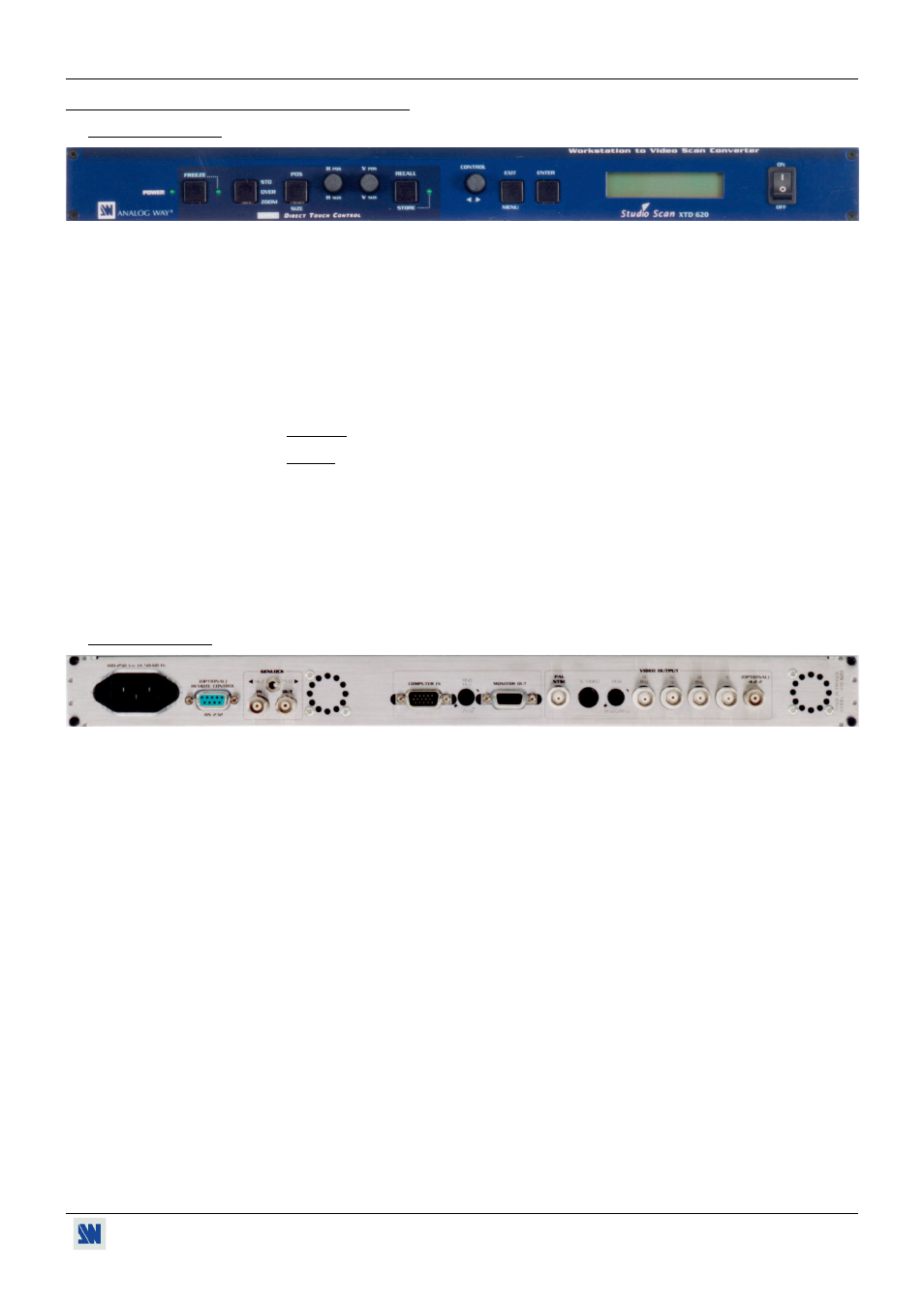
3-1. FRONT PANEL
POWER:
LED indication AC mains plugged.
FREEZE:
Allows to freeze the displayed image.
STD / OVER / ZOOM:
Standard / Overscan / Zoom Mode.
POS / SIZE:
Position or Size Image Mode (Controlled by the H & V buttons).
H.POS / H.SIZE:
Horizontal Image Control.
V.POS / V.SIZE:
Vertical Image Control.
RECALL / STORE:
RECALL (A Short push on the button): Allow to recall the Stored Image setting.
STORE (A Long push, LED = On) :Allow to store the Input format with his image setting.
CONTROL :
Allows to select items in the LCD menu.
EXIT MENU:
Allows to exit from an LCD menu.
ENTER:
Allows to validate a selected item.
LCD SCREEN:
Displays the device Status or the Control Menus.
ON / OFF:
AC power switch (O = OFF, I = ON).
3-2. REAR PANEL
POWER INPUT:
Standard IEC Connector (100-250VAC, 50-60Hz Automatic).
REMOTE CONTROL:
Standard RS-232, DB9 Female connector.
GENLOCK:
IN:
Input (BNC).
OUT:
Output (BNC).
Hi.Z / 75 Ohms:
Left Position = Hi.Z, Loopthrough.
Right Position = 75 Ohms.
COMPUTER IN:
Input PC (SUB-D HD15 Male).
RGB Hi.Z / 75 Ohms:
Push this button if a monitor is used.
MONITOR OUT:
Output PC (SUB-D HD15 Female).
PAL/NTSC:
Video Composite Output.
S.VIDEO:
Y/C Output (4 pin mini DIN).
RGB / Y, R-Y, B-Y:
Button to release for a component output (Y, R-Y, B-Y).
RGB / Y, R-Y, B-Y:
RGB/S, RGsB or YUV Output (BNC). To select RGsB or RGB/S, see Chapter 7 : LCD
FUNCTIONS DESCRIPTION.
4:2:2 (OPTIONAL):
Digital Video Output (D1), only active on XTD 620 - D1 version.