AMETEK MX Series Rev: AY User Manual
Page 247
User Manual - Rev AV
AMETEK Programmable Power
MX Series
247
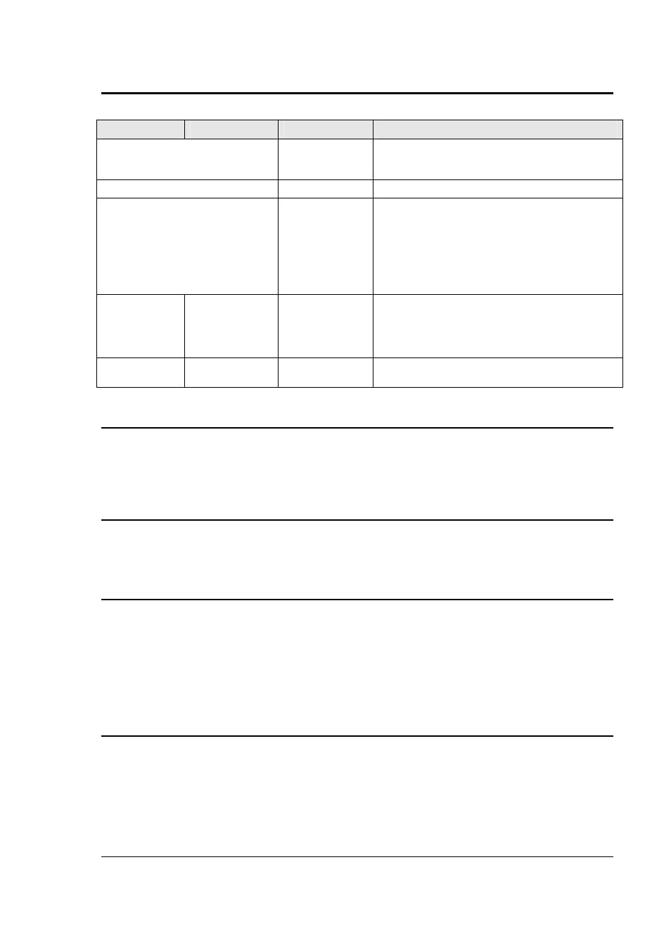
Field
Description
Setting Range
Purpose
Frequency Shift
application delay
time. (Delay F)
This delay determines how long the MX waits to apply
the programmed frequency shift to the EUT after the
set current limit level has been exceeded.
Output Relay
Open delay time.
Output Relay
Open delay time.
(Delay R)
This delay determines how long the MX waits to open
the output relay after the frequency shift has been
This delay determines how long the MX waits to open
the output relay after the frequency shift has been
applied and the current still exceeds the set current
limit level. If the frequency shift is set to 0.0Hz, this
setting determines the time the output relay will be
opened after the UNDER VOLTAGE is applied
CURR
Regen Current
Limit
This is the regenerate current limit set point that the
power source tries to limit the current to that is fed
back from the inverter. It is different from the normal
current limit set value shown in the PROGRAM
screen.
PREVIOUS
SCREEN
Returns to previous screen.
9.11.4 SNK Setting Retention
Parameters set in the REGENERATE CONTROL screen are retained in non-volatile memory
between uses except for the STATE field which always powers up in the OFF state. They are
NOT part of the setup registers however. Thus, only one set of parameters is retained reflecting
the last used settings.
9.11.5 SNK Remote Control
The same SNK parameters can also be programmed over any of the available remote control
interfaces using SCPI commands. Refer to the MX Programming Manual for details on
programming syntax.
9.11.6 SNK and Phase Modes
On MX models operating in three phase mode, the protection shut down mechanisms are
implemented on a phase by phase basis. This means that these parameters can be different for
each phase. To set all parameters to the same value for all three phases, use the PHASE button
on the front panel to select the ABC indication in the upper right corner of the LCD display. This
will allow you to set these values for all three phases. To set values by individual phase, use the
PHASE button to select either A, B, or C. The PHASE button cycles between A,B,C and ABC.
For three phase EUT’s, it is generally recommended to set the same values for all three phases.
9.11.7 Output Relay control while in Regen Mode
For some PV inverter tests, it may be necessary to ‘disconnect’ the inverter from the grid
(simulated by the power source). When the SNK state is ON, the OUTPUT relay control (Output
On/Off) will cause the output relay to open without the output voltage being dropped first. It is
important to make sure the inverter is in a balanced state with respect to its load so minimal
current flows into the power source. If not, the relay of the power source will be hot switched
which should be avoided.