4 remote monitoring, 5 remote digital status signals – AMETEK DCS-E 1kW Series Programming Manual User Manual
Page 31
DLM-E Series and DCS-E Series
Isolated Analog Programmer Operation
M51A Option
2-19
2.4 Remote
Monitoring
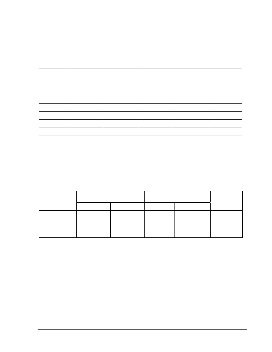
Analog signals are available for monitoring the output voltage and current. These signals vary
proportionally to the output parameters, and have user selectable ranges of 0-5VDC, 0-10VDC,
or 4-20mA for an output change from zero to full scale. Refer to Table 2–3 for information on
configuring the monitors.
Isolated Analog
Programmer Connector J4
SW1 SETUP Switch
Output
Monitor
Signal
Signal Return Position Setting
Signal
Range
Voltage
Pin-19
Pin-12
4 - V MON
ON (1)
0-10VDC
Voltage
Pin-19
Pin-12
4 - V MON
OFF (0)
0-5VDC
Voltage Pin-4 Pin-12 N/A N/A
4-20mA
Current
Pin-7
Pin-12
5 - I MON
ON (1)
0-10VDC
Current
Pin-7
Pin-12
5 - I MON
OFF (0)
0-5VDC
Current Pin-24 Pin-12
N/A N/A
4-20mA
Table 2–3. Remote Monitoring
2.5 Remote Digital Status Signals
Digital signals are available for remote monitoring the operational status of the unit. Refer to
Table 2–4 for information on the characteristics of the signals.
Isolated Analog Interface
Connector J4
Logic Levels (with No
Signal Output Current)
Status
Indicator
Signal
Signal Return
Asserted
Not
Asserted
Output
Resistance
VOLTAGE-
MODE
Pin-5 Pin-6 5V 0V 1kΩ
OVP Pin-17 Pin-6 5V 0V 1kΩ
FAULT Pin-18 Pin-6 5V
0V
1kΩ
Table 2–4. Remote Digital Status Signals