6 resistance programming of ovp – AMETEK DCS-E 1kW Series Programming Manual User Manual
Page 24
Isolated Analog Programmer Operation
DLM-E Series and DCS-E Series
2.3.6
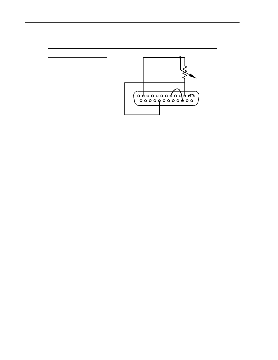
Resistance Programming of OVP
SW1 Switch Settings
SW1-3 ON (1) = 0–5K
2
3
6
12
13
1
25
14
16
21
Set up for resistance programming of the output voltage as follows:
1.
Set SW1-3, OVP PROG, to ON (1) for 0-5VDC programming range.
2.
Connect the external programming resistance, 0-5KΩ, to the ISOLATED ANALOG
PROGRAMMER connector, from Pin-3 to Pin-12.
3.
Connect a jumper from Pin-3 to Pin-21 or Pin-22, (whichever one is available) to connect
the 1mA current source.
4.
Connect Pin-1, ANALOG-CONTROL, of the ISOLATED ANALOG PROGRAMMER
connector, J4, to Pin-2 to enable remote control.
5.
Program the other parameters to the desired limit values.
6.
Connect Pin-16, OVP Default Programming Input, of the ISOLATED ANALOG
PROGRAMMER connector (J4) to Pin-6 to disable the default OVP programming
connection.
2-12
M51A Option