9 programming the shutdown function, 10 ttl shutdown – AMETEK DCS-E 1kW Series Programming Manual User Manual
Page 27
DLM-E Series and DCS-E Series
Isolated Analog Programmer Operation
2.3.9 Programming
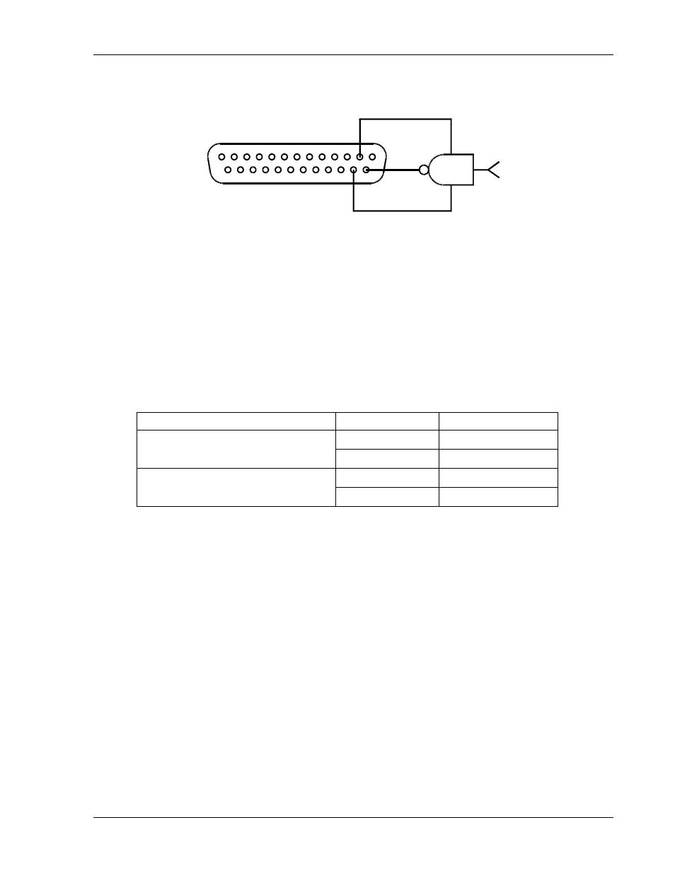
the Shutdown Function
2
13
1
25
15
+5V
GND
14
Figure 2–3. Using Shutdown with a DC Input (Positive Logic)
2.3.10 TTL
Shutdown
Set up for Shutdown input signal as follows:
1.
Connect the shutdown signal source to the ISOLATED ANALOG PROGRAMMER
connector, J4, with positive to Pin-14 and the return to Pin-2.
2.
Set switch SW1-6 to select the desired logic as defined in the following table.
Switch SW1-6 Setting
Signal Level
Output Condition
Low OFF
OFF (0) =
Negative Logic
High ON
High OFF
ON (1) =
Positive Logic
Low ON
M51A Option
2-15
This manual is related to the following products: